Physical Issues
Cable Issues
Using the correct fiber optics
Fiber mismatching
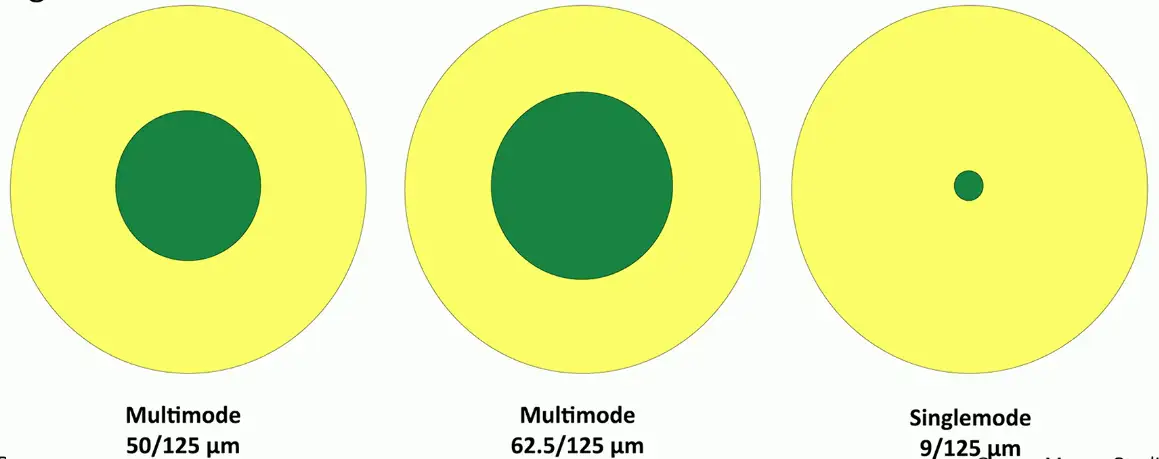
Core and cladding sizes are relatively standard
- Fiber and frequencies must match equipment
- Signal errors will be seen on the interface
There will be writing on the cable about size and type.
Cable Categories
Cable construction is standardized
- Telecommunication Industry Association (TIA)
TIA sets the minimum physical cable parameters
- Cables meeting the standard are assigned a category (cat)
- Insertion loss, near end crosstalk, far end crosstalk, etc.
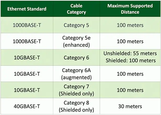
IEEE networking standards refer to the TIA cable categories
- 1000BASE-T minimum cable is category 5
- 10GBASE-T minimum cable is category 6 and 6A
Using the right cable
Speed/bandwidth
- Theoretical maximum data rate
- Usually measured in bits per second
- The size of the pipe
Throughput
- Amount of data transferred in a given timeframe
- Usually measured in bits per second
- How much water is flowing through the pipe
Distance
- Know the maximum distance
- Varies based on copper, fiber, repeaters, etc.
The right cable category
Validate the cable
- Use best practices during installation
- Tester matches to the closest cable category
Cable should meet the minimum requirements
- Physical errors will increase error counts
- Signal attenuation (transmission loss), loss of signal, CRC errors
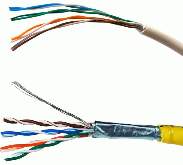
Unshielded and shielded cable
UTP (Unshielded Twisted Pair)
- No additional metal shielding
- The most common twisted pair cabling
STP (Shielded Twisted Pair)
- Additional shielding protects against interference
- Shield each pair and/or the overall cable
- Requires the cable to be grounded
Crosstalk (XT)
Signal on one circuit affects another circuit
- In a bad way
Leaking of signal
- You can sometimes hear the leak
Measure XT with cable testers
- Some training may be required
Crosstalk metrics
Near End Crosstalk (NEXT)
- Interference measured at the transmitting end
- The near end
Far End Crosstalk (FEXT)
- Interference measured at away from the transmitter
Alien Crosstalk (AXT)
- Interference from other cables
Attenuation to Crosstalk Ratio (ACR)
- Difference between insertion loss and NEXT
- Signal-to-Noise Ratio (SNR)
Troubleshooting Crosstalk
Almost always a wiring issue
- Check your crimp
Maintain your twists
- The twist helps to avoid crosstalk
Category 6A increases cable diameter
- Increased distance between pairs
Test your installation
- Solve problems before they are problems
Avoiding EMI and Interference
Electromagnetic interference
Cable handling
- No twisting — don’t pull or stretch
- Watch your bend radius
- Don’t use staples, watch your cable ties
EMI and interference with copper cables
- Avoid power cords, fluorescent lights, electrical systems, and fiber prevention components
Test after installation
- You can find most of your problems before use
Attenuation
Usually gradual
- Signal strength diminishes over distance
- Loss of signal intensity as signal moves through a medium
Happens across all mediums
- Electrical signals through copper
- Light through fiber
- Radio waves through the air
Troubleshooting termination
Cables can foul up a perfectly good plan
- Test your cables prior to implementation
Many connectors look alike
- Do you have a good cable mapping device?
Get a good cable person
- It’s an art (REALLY!)
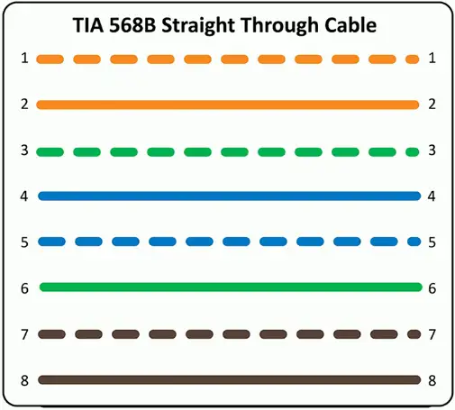
Improper Termination
Near and far pins in cables aren’t where they are supposed to be
- Pin 1 goes to pin 1, pin 2 to pin 2, etc.
Performance or connectivity issues
- May drop from 1 Gbit/sec to 100 Mbit/sec
- May not connect at all
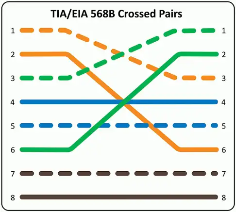
Reversing transmit and receive
Wiring mistake
- Cable ends
- Punch downs
Easy to find with a wire map
- 1-3, 2-6, 3-1, 6-2
- Simple to identify
Some network interfaces will automatically correct (Auto-MDIX)
- Don’t rely on this functionality
Interface Issues
Monitoring the interface
Often your first sign of trouble
- The local problems are easy to attack
Can sometimes indicate a bigger issue
- Problem with a switch or congestion in the network
View in the OS
- Interface details
Monitor with SNMP
- Remote monitoring of all devices
- Most metrics are in MIB-II
- Proprietary MIB may be available
Interface Monitoring
Link status
- Link up, or link down?
- May be a problem on the other end of the cable
Utilization
- Per-interface network usage
- Run bandwidth tests to view throughput
Error rate
- Problems with the signal
- CRC errors, runts, giants, drops
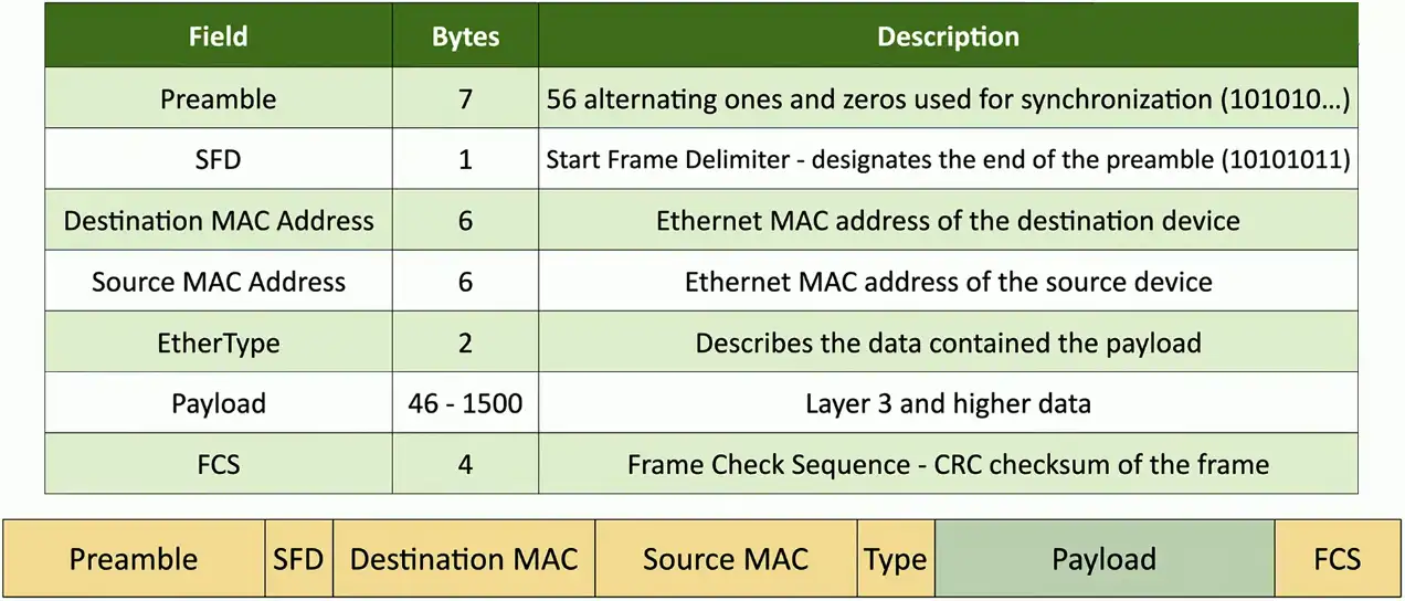
The Ethernet Frame
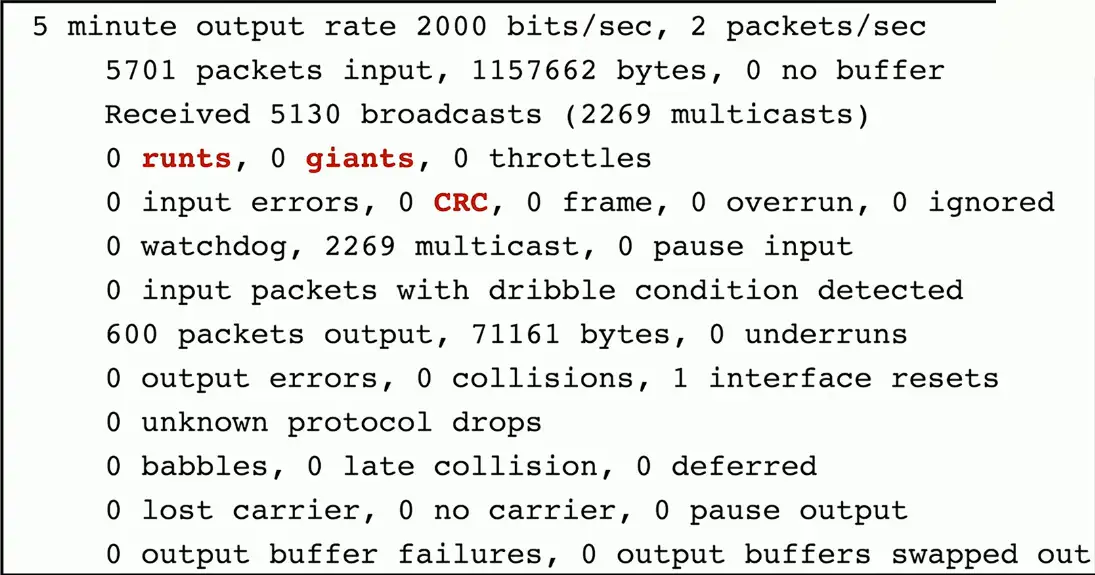
Counting the Errors
CRC (Cyclic Redundancy Check) error detecting
- Add a frame check sequence to an Ethernet frame
- Receive the frame, recalculate the CRC, and compare to the original
- Non-matching CRC is an error
Runts — Frames that are less than 64 bytes
- May be a result of a collision
Giants — Frames that are more than 1518 bytes
- Or more than the configured maximum frame size
Drops
- Frames not transmitted or received due to contention
#show interfaces f0/1
Error disabled
Some problems should be stopped in their tracks
- They go on and on
Disable the interface to fix the symptom
- This does not fix the problem
Many reasons
- Link flapping (up/down), port security violations, duplex mismatch, etc.
Must be administratively re-enabled
- Intervention is required
Port status
Administratively down
- The device admin has “turned off” an interface
- This was intentional
- Does not work again until administratively enabled
Suspended
- The configuration is not compatible with the current connection
- This is similar in function to “error disabled”, but occurs immediately
- Set LACP (Link Aggregation Control Protocol) on one side, but not the other
Hardware Issues
Power over Ethernet (PoE)
Power provided on an Ethernet cable
- One wire for both network and electricity
- Phones, cameras, wireless access points
- Useful in difficult-to-power areas
Power provided at the switch
- Built-in power — Endspans
- In-line power injector — Midspans
PoE, PoE+, PoE++
PoE
- The original PoE specification
- 15.4 watts DC power, 350 mA max current
PoE+
- 25.5 watts DC power, 600 mA max current
PoE++
- 51 W (type 3), 600 mA max current
- 71.3 W (type 4), 960 mA max current
- PoE with 10GBASE-T
Compare the device with the switch support
- PoE+ won’t power a PoE++ device
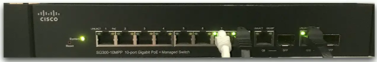
PoE switch
Power over Ethernet interfaces
- Commonly marked on the switch or interfaces
Check switch for total PoE power supported
- “Up to 600 watts”
- Calculate the device requirements for the power budget
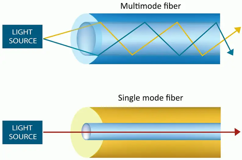
Single mode vs. multimode
Transceivers have to match the fiber
- Single mode transceiver connects to single mode fiber
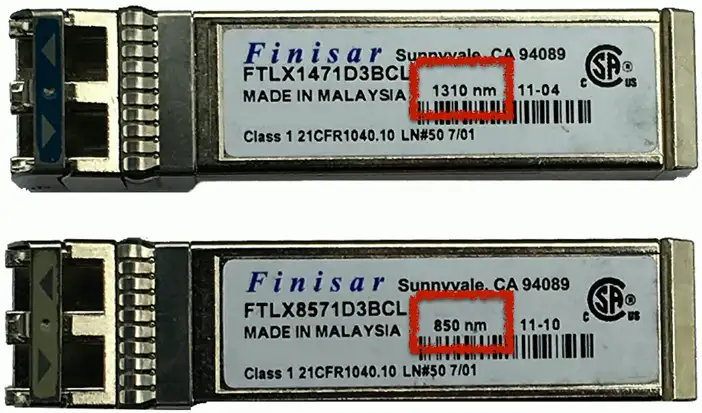
Transceiver needs to match the wavelength
- 850 nm, 1310 nm, etc.
Use the correct transceivers and optical fiber
- Check the entire link
Signal loss
- Dropped frames, missing frames
Transceiver mismatch
May look the same, but work on different wavelengths
Transceiver signal strength
Devices must receive enough signal
- Can’t work if the signal isn’t strong enough
Each device has a sensitivity level
- Some devices can “hear” better than others
Calculate the power budget
- Determine transmitter power (often measured in dBm)
- Calculate signal loss based on distance, connectors, splices, etc.
- Subtract signal loss from the transmitter power
- Compare to minimum receive power
