Switching Technologies
Media Access Control (MAC) Address
A 48-bit unique identifier for an Ethernet client.
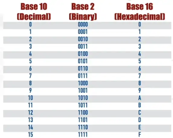
- MAC represented as hexadecimal notation
Hexadecimal numbering with Base 10, and Base 2 number:
Organizationally Unique Identifier (OUI): A 24-bit string assigned to a vendor of Ethernet hardware.
- First 24-bit of MAC address
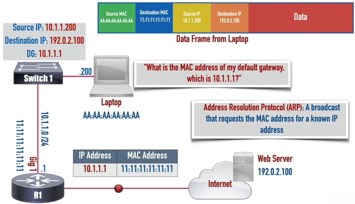
A data frame also needs MAC address to reach its destination
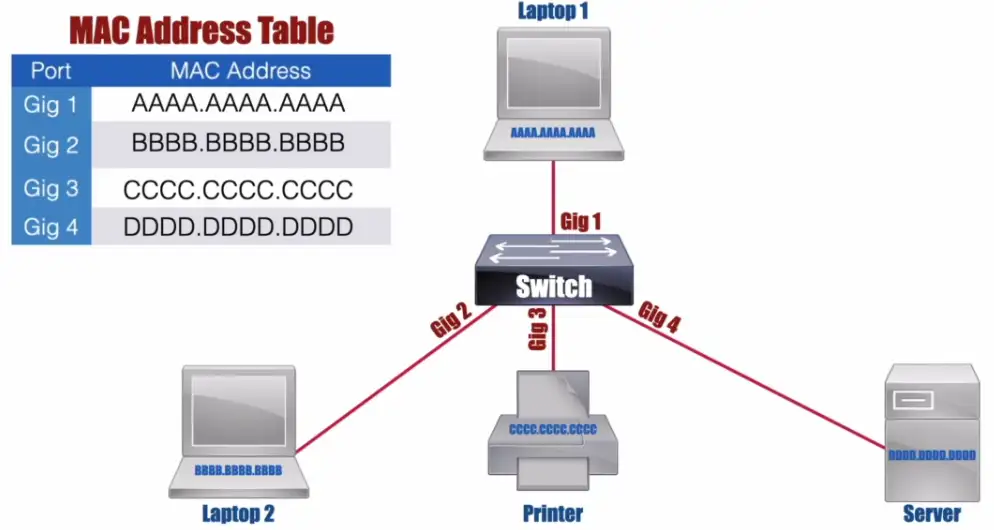
Ethernet Switch Frame Forwarding
- Based on MAC address
- Happens at layer 2
- Switch maintains a MAC Address Table
Flooding: Occurs when an Ethernet switch sends a copy of an incoming frame out all of its ports, other than the port on which the frame was received. Because the switch hasn’t learned the port off of which the destination MAC address is connected.
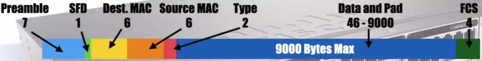
- Ethernet Frame has an 18 Bytes Header
- Preamble and SFD are part of Layer 1, used for synchronization

- Ethernet Jumbo Frame Format
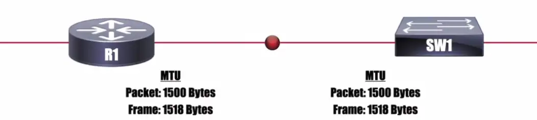
MTU (Maximum Transmission Unit): The maximum size (measured in Bytes) of a packet or frame allowed on an interface.
VLANs and Trunking
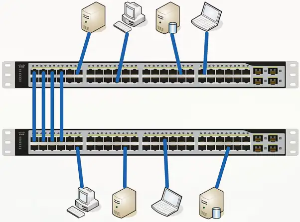
LANs
Local Area Networks
- A group of devices in the same broadcast domain
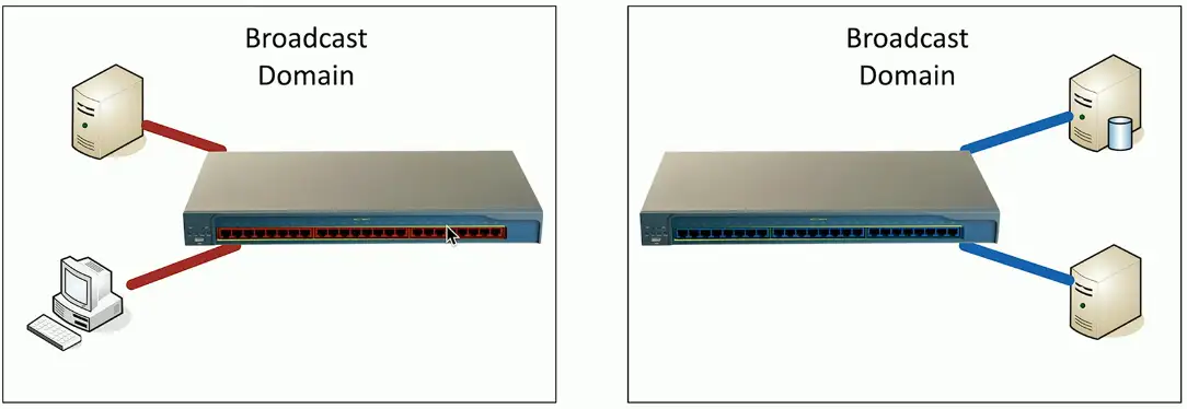
- Two switches, taking power
- Using double the rack space
- Harder to manage
Virtual LANs
Virtual Local Area Networks
- A group of devices in the same broadcast domain
- Separated logically instead of physically
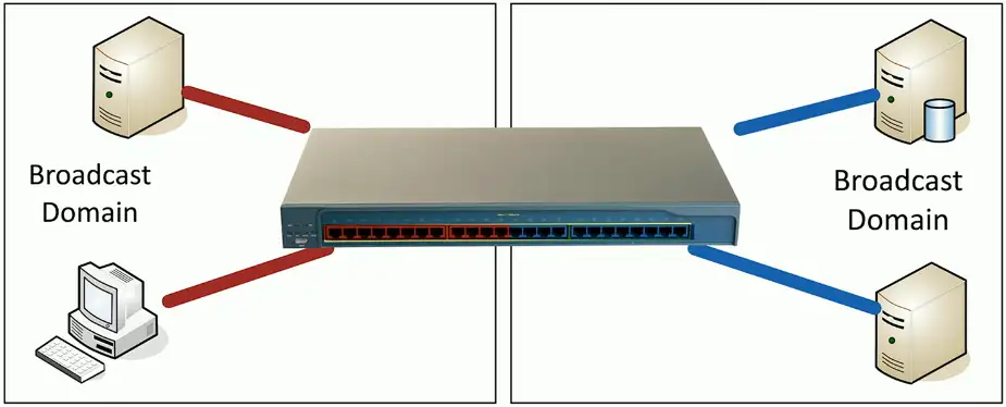
- One switch to manage, less power usage
- Cheaper to manage
- Lesser rack space
- Red and Blue VLANs will not be to communicate between them like physical LANs, except inside the red/blue VLAN only.
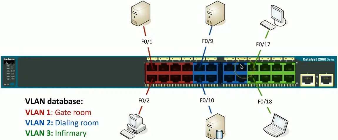
Configuring VLANs
VLAN numbers and names are configured in the switch
- The VLAN database
- Instead of color, VLANs are represented by number, VLAN1, VLAN2 etc.
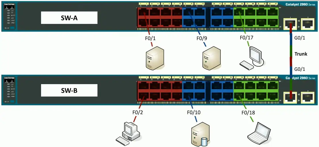
VLANs on multiple switches
We want to communicate among VLAN1s on multiple switches
- One simple fix is to connect both VLAN100 on each switch with an Ethernet cable
- But, it quickly gets complicated when there are hundreds of switches with VLANs.
VLAN Trunking
“VLAN trunking is a technology that allows multiple VLANs to share a single physical link between network switches. Instead of needing separate cables for each VLAN, a trunk link carries traffic for all VLANs simultaneously while keeping them logically separated.”
- Trunk carry traffic for multiple VLANs
- Trunk interface is used to connect VLANs on different physical switches.
- Single cable to carry packet for all switches
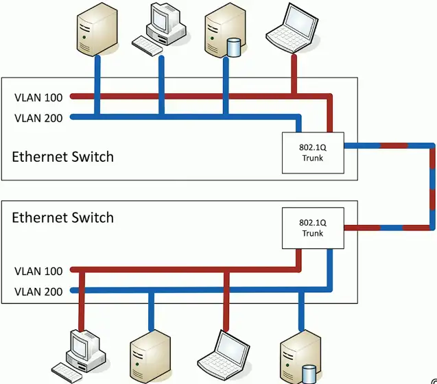
802.1Q trunking
How trunking identifies which packet belongs to which VLAN interface? By tagging!
- Take a normal Ethernet frame

- Add a VLAN header in the frame

- VLAN IDs – 12 bits long, 4,096 VLANs
- “Normal range” – 1 through 1005, “Extended range” – 1006 through 4094 – 0 and 4,095 are reserved VLAN numbers
- Before 802.1Q, there was ISL (Inter-Switch Link)
- ISL is no longer used; everyone now uses the 802.1Q standard
VLAN trunking:
- VLAN200 wants to send an Ethernet frame to VLAN200 on the other physical switch
- VLAN200 sends normal packet to the trunking interface
- Trunk adds a tag (VLAN200)
- Sends the frame to other VLAN200 device on the different switch
- The switch at the other receives the frame, sees the tag VLAN200, removes the tag, and sends it to the VLAN200.
Trunking between switches:
- It now needs a single packet to connect VLANs on different physical switches
The Native VLAN
This is different from the “default VLAN”
- The default VLAN is the VLAN assigned to an interface by default
Each trunk has a native VLAN
- The native VLAN doesn’t add an 802.1Q header
The native VLAN connects switches without a tag
- Some devices won’t talk 802.1Q
- Just use the native VLAN!
Native VLAN should match between switches
- You’ll get a message if the VLAN IDs don’t match
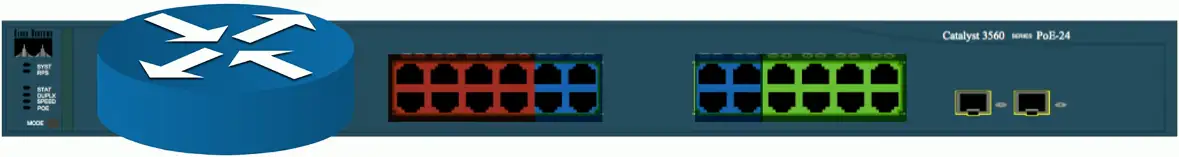
Layer 3 switches
A switch (layer 2) and router (layer 3) in the same physical device
- Layer 2 router?
Switching still operates at OSI Layer 2, routing still operates at OSI Layer 3
- There is nothing new or special happening here
- Just saving a space by putting the switch and router in a single physical device
The internal router connects to the VLANs over VLAN interfaces
- Also called switched virtual interfaces (SVI)
May need to enable routing on your switch
- Will operate as an L2 device until enabled
- May require a switch restart
Doesn’t replace a standalone router
- Not all designs require extensive routing
- You probably use a layer 3 switch at home
Working with Data and Voice
Voice VLAN: A VLAN that can be configured on an Ethernet switch for the purpose of carrying voice packets to and from IP phones.
Old school: Connect computer to switch, connect phone to PBX (Private Branch Exchange)
- Two physical cables, two different technologies
Now: Voice over IP (VoIP)
- Connect all devices to the Ethernet switch
- One network cable for both
Three ways to carry voice and data traffic:
- Connect the voice and data to the same switch port, when there is the software based IP phone.
- Connect the Cisco IP phone to Cisco switch (which supports two vLANs on a single port, one should carry voice), Cisco uses CDP (Cisco Discovery Protocol) a proprietary protocol to identify voice and data on a single port.
- Use a native port for data and VLAN for voice.
There is also vendor natural LLDP (Link Layer Discovery Protocol), which works at Layer 2, but not compatible with Cisco switches. It’s IEEE 802.1AB standard, used by network devices to advertise their identity, capabilities, and neighbors on a local area network.
There is also LLDP-MED, an extension to LLDP protocol known as LLDP Media Endpoint Discovery. It provides additional features for voice and video applications, including auto-discovery of LAN policies (VLAN, QoS), device location for emergency services, and Power over Ethernet (PoE) management.
Data and Voice cabling
- Computer connects to phone
- Phone connects to switch
- One cable, one run
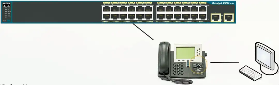
Just one problem…
Voice and data don’t like each other
- Voice is very sensitive to congestion
- Data loves to congest the network
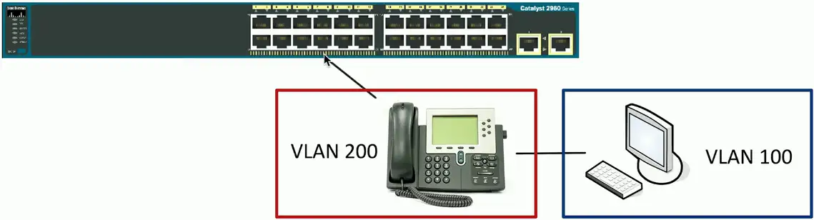
Put the computer on one VLAN and the phone on another
- But the switch interface is not a trunk
- How does that work?
Each switch interface has a data and a voice VLAN
- Configure each of them separately
Configuring Voice and Data VLANs
- Data passes as a normal untagged access VLAN
- Voice is tagged with an 802.1Q header
Interface Configuration
Speed and duplex
- Speed: 10/100/1,000/10 Gig
- Speed mismatch between switches, connection will not work at all.
- Duplex Half/Full
- Duplex mismatch, the connection will work but with degraded performance
- Automatic and manual
- Needs to match on both sides
IP address management
- Layer 3 interfaces
- VLAN interfaces
- Management interfaces
- IP address, subnet mask/CIDR block, default gateway, DNS (optional)
Link Aggregation
Port bonding/Link aggregation (LAG)
- Multiple interfaces act like one big interface
- Four 10 Gbits interfaces will act as a single 40 Gbits interface
LACP
- Link Aggregation Control Protocol
- Adds additional automation and management
Maximum Transmission Unit (MTU)
The largest frame or packet that can be transmitted or received on an interface.
- But not fragment
Fragmentation slows things down
- Losing a fragment loses an entire packet
- Requires overhead along the path
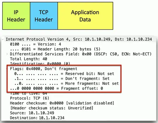
- Don’t Fragment (DF) Bit: A bit in an IPv4 header that prevents a packet from being fragmented.
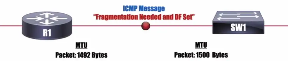
NOTE: IPv6 doesn’t have a DF bit, and it uses a “Packet Too Big” ICMPv6 message.
Difficult to know the MTU all the way through the path
- Automated methods are often inaccurate
- Especially when ICMP is filtered
Jumbo Frames
Ethernet frames with more than 1,500 bytes of payload
- Up to 9,216 bytes of an MTU (9,000 is the accepted norm)
Increases transfer efficiency
- Per-packet size
- Fewer packets to switch/route
Ethernet devices must support jumbo frames
- Switches, interface cards
- Not all devices are compatible with others
Spanning Tree Protocol
Loop Protection
Connect two switches to each other
- Create a loop with two cables
- They will send traffic back and forth forever
- There’s no “counting” mechanism at the MAC layer
This is an easy way to bring down a network
- And somewhat difficult to troubleshoot
- Relatively easy to resolve
IEEE standard 802.1D to prevent loops in bridged (switched) networks (1990)
- Spanning Tree Protocol
- Used practically everywhere
STP Port States
Blocking
- Not forwarding to prevent a loop
Listening
- Not forwarding and cleaning the MAC table
Learning
- Not forwarding and adding to the MAC table
Forwarding
- Data passes through and is fully operational
Disabled
- Administrator has turned off the port
Spanning Tree Protocol
If Network A wants to communicate with Network M, it can use Bridge 6
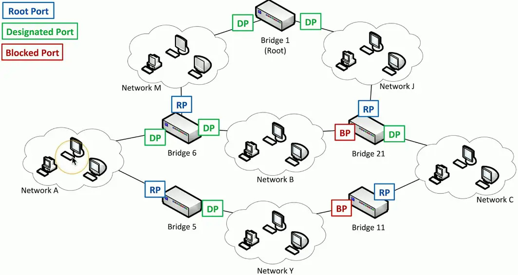
If bridge 6 is unavailable for some reason, there is no other available root!!!
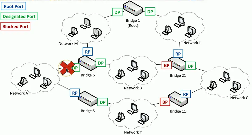
Spanning Tree recognizes the disconnection, and starts relearning the topology of the network, to clear out congestion. It reconfigures the STP port states to reestablish the connection between Network A and Network M through Bridge 5.

RSTP (802.1w)
Rapid Spanning Tree Protocol (802.1w)
- A much-needed updated version of STP
- This is the latest standard
Faster convergence
- From 30 to 50 seconds to 6 seconds
Backwards-compatible with 802.1D STP
- You can mix both in your network
Very similar process
- An update, not a wholesale change