This course is freely available on YouTube, thanks to Professor Messer. Please support Professor Messer directly by buying his official Network+ Notes.
This course is offered by Kevin Wallace. It is currently drafted on Udemy, no enrollment possible. But you can enroll in any of the newer Kevin Wallace courses over on his website.
Info
I would primarily follow Professor Messer’s Network+ YouTube playlist for notes taking. Please check official CompTIA Network+ page for latest news, exam resources, and exam products.
Each grain of sand on Earth could have 45 quintillion unique IPv6 addresses
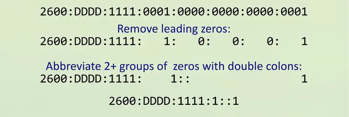
IPv6 address compression
Groups of zeros can be abbreviated with a double colon ::
Only one of these abbreviations allowed per address
Leading zeros are options:
Communicating between IPv4 and IPv6
Not all devices can talk IPv6
Legacy devices, embedded systems, etc.
How can an IPv4 device talk to an IPv6 server?
Can an IPv6 device communicate with a legacy IPv4 server?
Requires an alternate form of communication
Tunnel — Encapsulate one protocol within another
Dual-stack — Have the option to use both IPv4 and IPv6
Translate — Convert between IPv4 and IPv6
These are short-term strategies
Long-term goal should be a complete migration to IPv6
Tunneling IPv6
A migration option
Designed for temporary use
6to4 addressing
Send IPv6 over an existing IPv4 network
Creates an IPv6 address based on the IPv4 address
Requires relay routers
No support for NAT
No longer available as an option on Windows
4in6 tunneling
Tunnel IPv4 traffic on the IPv6 network
Dual-stack routing
Dual-stack IPv4 and IPv6
Run both at the same time
Interfaces will be assigned multiple address type
IPv4
Configured with IPv4 addresses
Maintains an IPv4 routing table
Uses IPv4 dynamic routing protocols
IPv6
Configured with IPv6 addresses
Maintains a separate IPv6 routing table
Uses IPv6 dynamic routing protocols
Translating between IPv4 and IPv6
Network address translation using NAT64
Translate between IPv4 and IPv6
Seamless to the end user
Requires something in the middle to translate
IPv6 is not backwards compatible with IPv4
Use a NAT64-capable router
Works with a DNS64 server
Translate the DNS requests
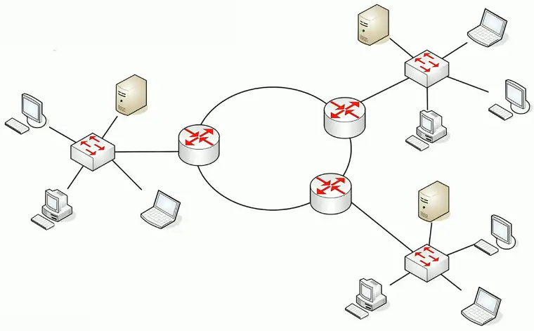
Routing Technologies
Static Routing
Routing Tables
The router has a relatively simple job
The underlying technology is relatively complex
Identify the destination IP address
It’s in the packet
If the destination IP address is on a locally connected subnet
Forward the packet to the local device
If the destination IP address is on a remote subnet
Forward to the next-hop router/gateway
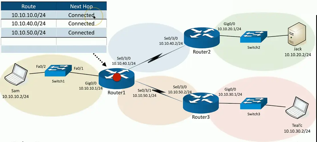
This “map” of forwarding locations is the routing table
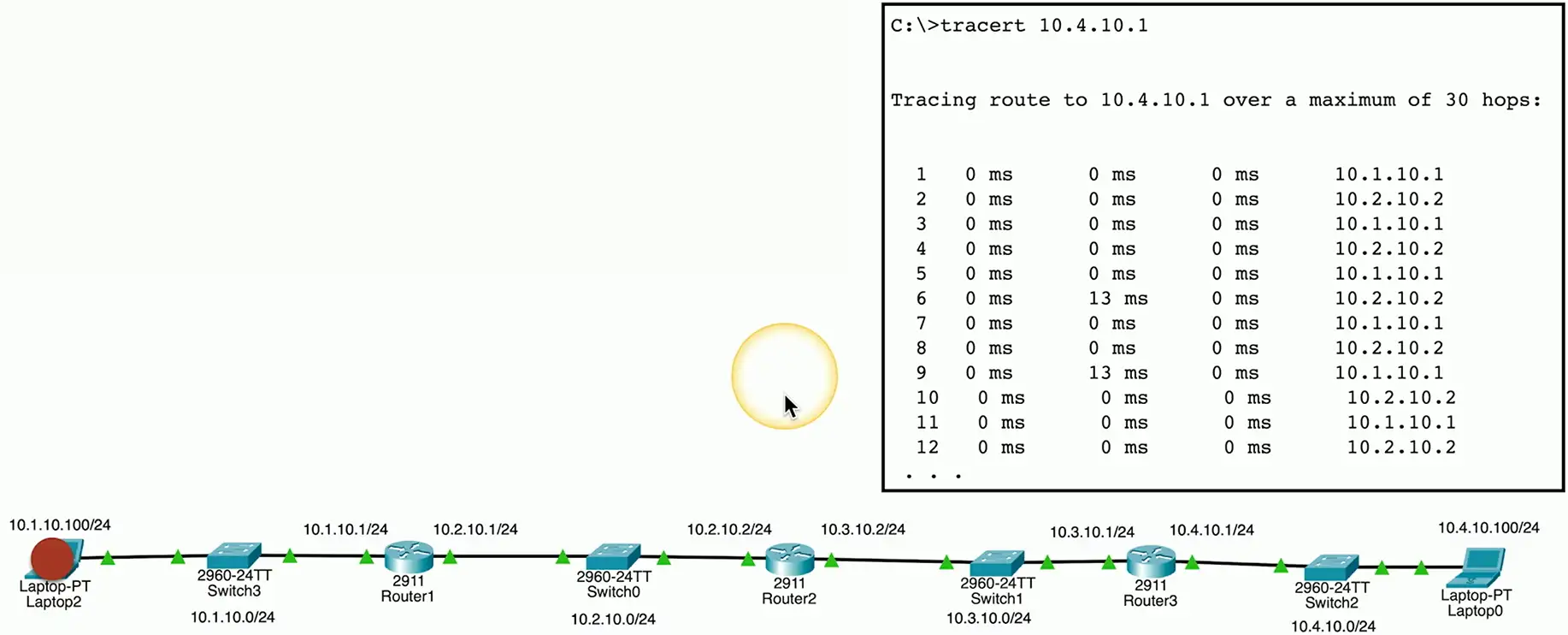
Routing the packets:
Static Routing
Administratively define the routes
You are in control
Advantages
Easy to configure and manage on smaller networks
No overhead from routing protocols (CPU, memory, bandwidth)
Easy to configure on stub networks (only one way out)
More secure — no routing protocols to analyze
Disadvantages
Difficult to administer on larger networks
No automatic method to prevent routing loops
If there’s network change, you have to manually update the routes
No automatic rerouting if an outage occurs
Dynamic Routing
Routers send routes to other routers
Routing tables are update in (almost) real-time
Advantages
No manual route calculations or management
New routes are populated automatically
Very scalable
Disadvantages
Some router overhead required (CPU, memory, bandwidth)
Requires some initial configuration to work properly
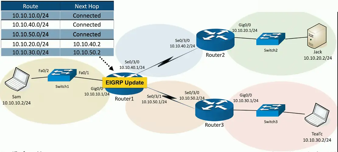
EIGRP Update
Enhanced Interior Gateway Routing Protocol
EIGRP is used to exchange routing information between routers
CISCO controlled proprietary protocol
Not widely adopted except on Cisco and partners devices
OSPF
Open Shortest Path First
It is a link-state routing protocol used to calculate the best path for data transmission within an IP network
Fully open standard
Vendor neutral
Dynamic Routing Protocols
Listen for subnet information from other routers
Sent from router to router
Provide subnet information to other routers
Tell other routers what you know
Determine the best path based on this information
Every routing protocol has its own way of doing this
When network changes occur, update the available routes
Different convergence process for every dynamic routing protocol
Which routing protocol to use?
What exactly is a route?
Is it based on the state of the link?
Is it based on how far away it is?
How does the protocol determine the best path?
Some formula is applied to the criteria to create a metric
Rank the routes from best to worst
Recover after a change to the network
Convergence time can vary widely between routing protocols
Standard or proprietary protocol?
OSPF and BGP are standards, some functions of EIGRP are Cisco proprietary
Enhanced Interior Gateway Routing Protocol
EIGRP
Partly proprietary to Cisco
Commonly used on internal Cisco-routed networks
Relatively easy to enable and use
Cleanly manage topology changes
Speed of convergence is always a concern
Loop free operation
Minimize bandwidth use
Efficient discovery of neighbor routers
OSPF
Open Shortest Path First
A common interior gateway protocol
Used within a single autonomous system (AS)
A well-established standard
Available on routers from many manufacturers
Link-state protocol
Routing is based on the connectivity between routers
Each link has a “cost”
Throughput, reliability, round-trip time
Low cost and fastest path wins, identical costs are load balanced
BGP (Border Gateway Protocol)
Exterior gateway protocol
Connect different autonomous system (AS)
The “three-napkins protocol”
Sketched out to solve an immediate problem
Turned into one of the most popular
A popular standard
Used around the world for Internet routing
Routing Technologies
Building a routing table
Routers are digital direction sign
How to I get to Google? Go that way.
Every IP device has a routing table
Workstations, servers, routers, etc.
The list of directions is the routing table
The most specific route “wins”
Sometimes there’s a tie
Duplicate destinations in the table
Which do you choose
There are ways to break the tie
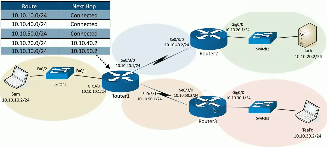
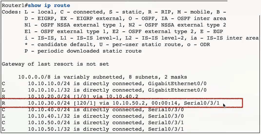
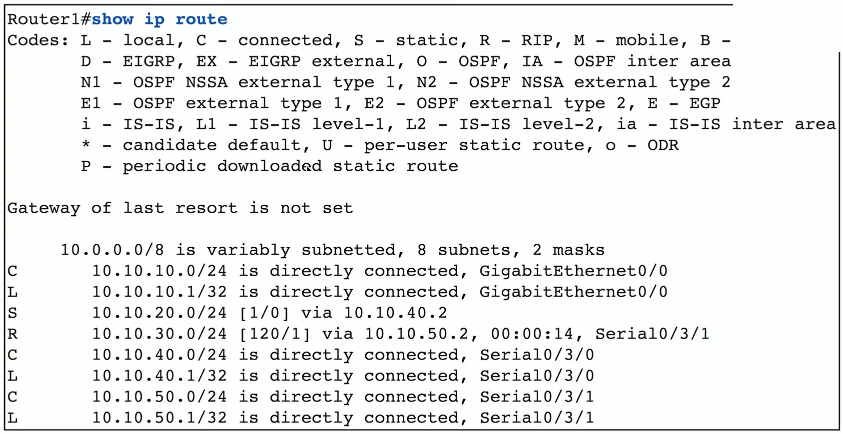
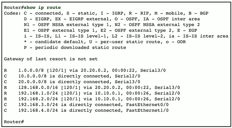
Routing table with RIPv2
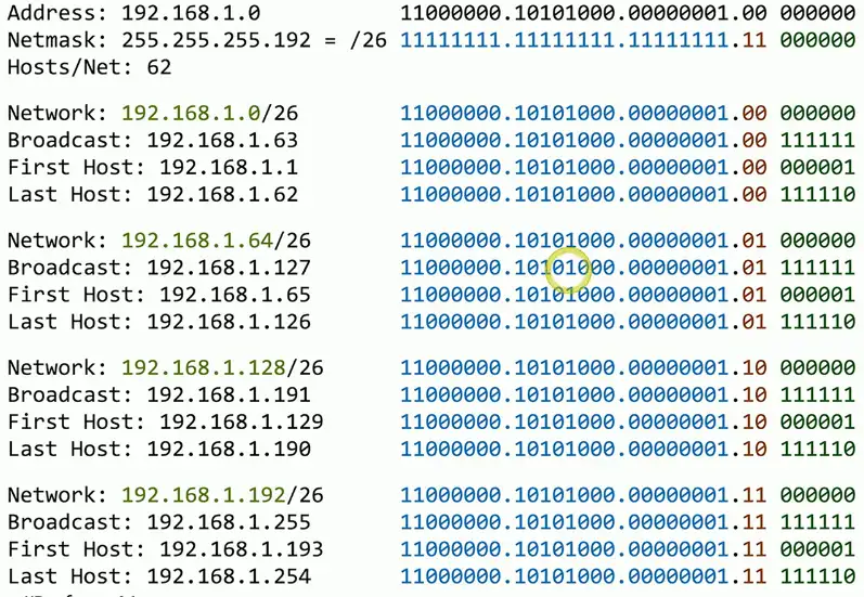
Prefix Lengths
Most specific route “wins”
A combination of the subnet ID and prefix length
Routes are more specific as the prefix increases
Router forwards traffic to the most specific destination
Pick the best route to a server with the address of 192.168.1.6
192.168.0.0/16
192.168.1.0/24 (2nd best route with narrow host range than /16)
192.168.1.6/32 (Best route, individual IP)
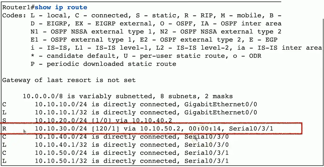
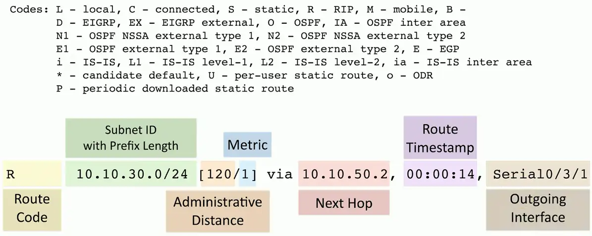
Administrative Distances
What if you have two routing protocols, and both know about a route to a subnet?
Two routing protocols, two completely different metric calculations
You can’t compare metrics across routing protocols
Which do you trust the most?
Administrative distances
Used by the router to determine which routing protocol has priority
Source
Administrative Distance
Local
0
Static route
1
EIGRP
90
OSPF
110
RIPv1 and RIPv2
120
DHCP default route
254
Unknown
255
Routing Metrics
Each routing protocol has its own way of calculating the best route
BGP, OSPF, EIGRP
Metric values are assigned by the routing protocol
BGP metrics are not useful to OSPF or EIGRP
Use metrics to choose between redundant links
Choose the lowest metric, i.e., 1 is better than 2
Routing table with RIPv2:
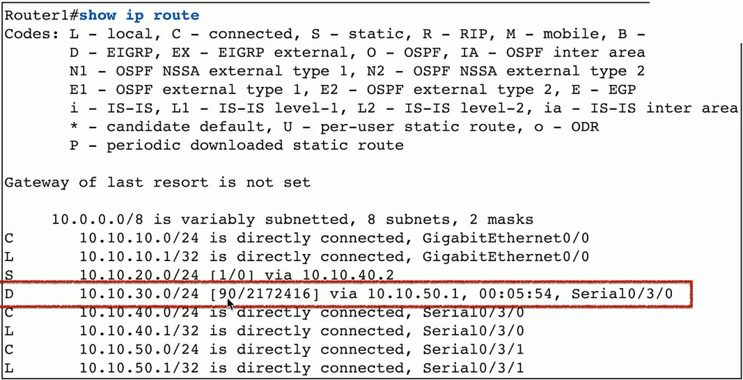
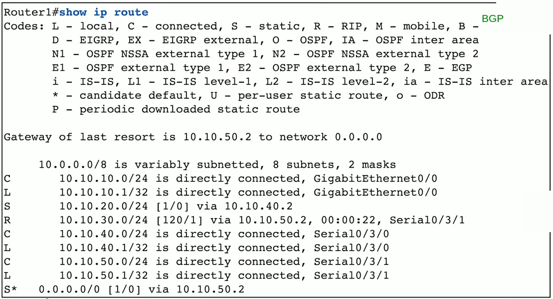
Routing table with EIGRP:
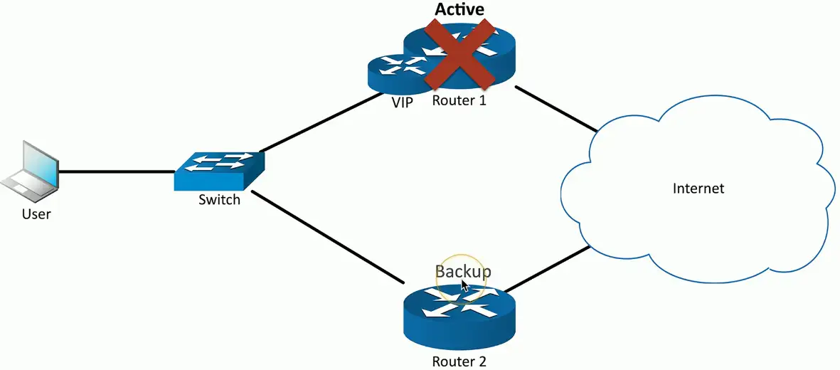
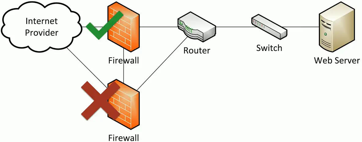
First Hop Redundancy Protocol (FHRP)
Your computer is configured with a single default gateway
We need a way to provide uptime if the default gateway fails
The default router IP address isn’t real
Devices use a virtual IP (VIP) for the default gateway
If a router disappears, another one takes its place
Data continues to flow
Solves a shortcoming with IP addressing
One default gateway can really be many routers
A network with two routers, one acting as a backup, fails:
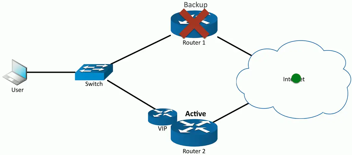
Backup router takes over, and the inactive router will be marked as backup:
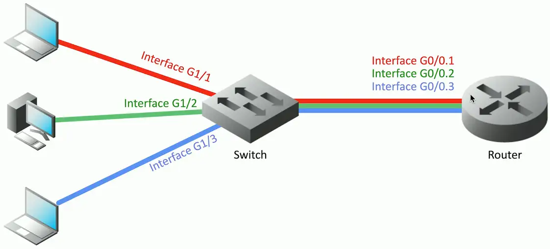
Subinterfaces
A device has a physical interface
Configure options for each interface
Some interfaces are not physical
VLANs in a trunk
These are subinterfaces
Often referenced with the physical
Interface Ethernet1/1
Subinterface Ethernet1/1.10
Subinterface Ethernet1/1.20
Subinterface Ethernet1/1.100
Network Address Translation (NAT)
It is estimated that there are over 20 t 30 billion devices connected to the Internet (and growing)
IPv4 supports around 4.29 billion addresses
The address space for IPv4 is exhausted
There are no available addresses to assign
How does it all work?
Network Address Translation
This isn’t the only use of NAT
NAT is handy in many situations
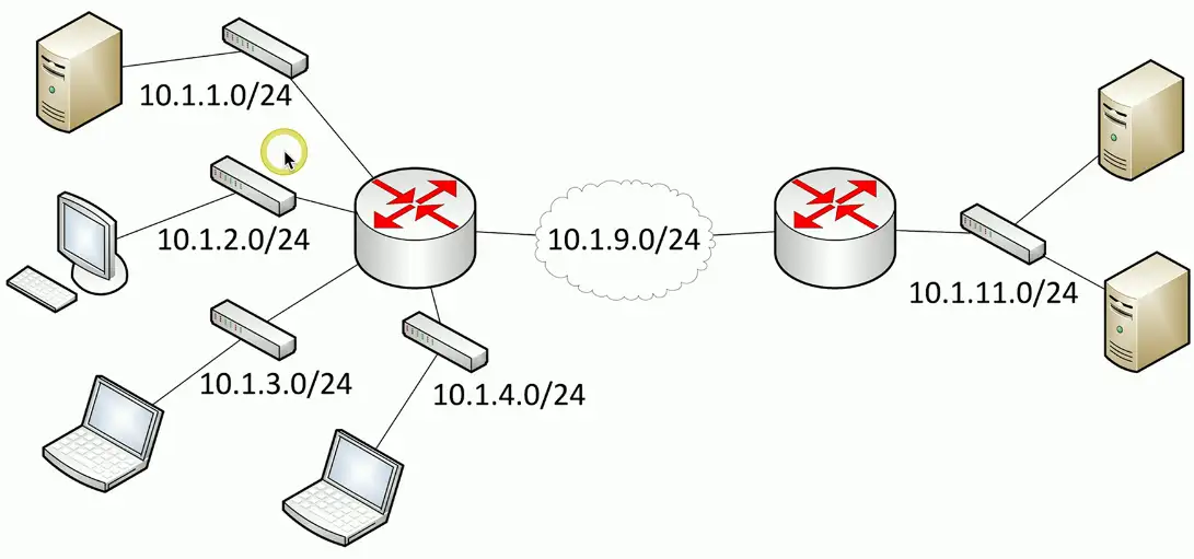
Public addresses vs. Private addresses
RFC 1918 private IPv4 addresses
IP address range
Number of addresses
Classful description
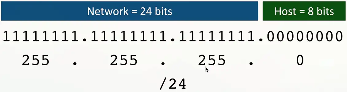
Largest CIDR block (subnet mask)
Host ID size
10.0.0.0 – 10.255.255.255
16,777,216
single class A
10.0.0.0/8 (255.0.0.0)
24 bits
172.16.0.0 – 172.31.255.255
1,048,576
16 contiguous class Bs
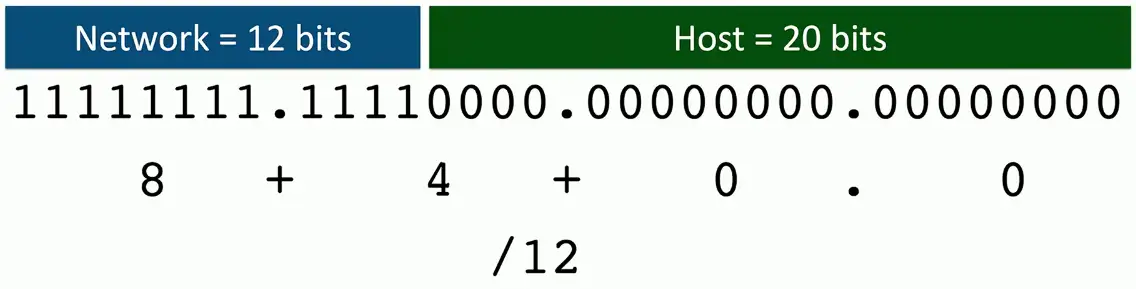
172.16.0.0/12 (255.240.0.0)
20 bits
192.168.0.0 – 192.168.255.255
65,536
256 contiguous class Cs
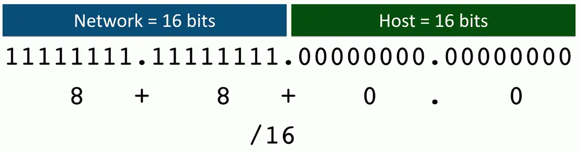
192.168.0.0/16 (255.255.0.0)
16 bits
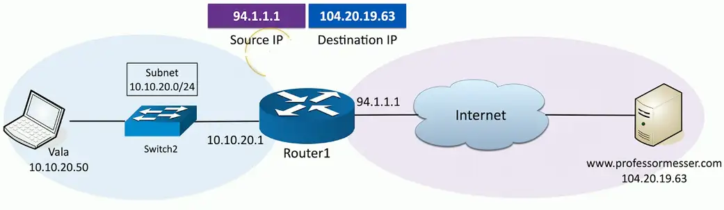
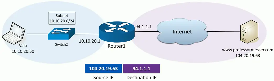
Network address translation:
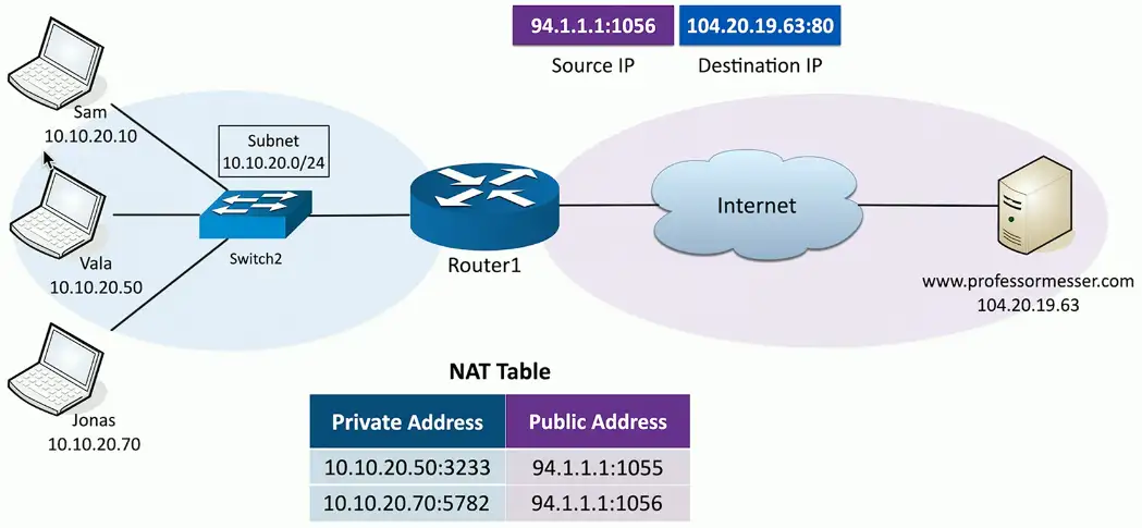
NAT overload/PAT
If we need to perform NAT for many computers on the network at the same, we need more public IP addresses to be available. To do this efficiently, we use NAT overload/PAT (Port Address Translation) protocol.
More than one device on the network
Want to reach to the same server on the Internet
They will be assigned Private Addresses with random port numbers and associated Public IPs with random port numbers.
The request goes to the destined server with the associated with Public IPs and port numbers.
The server with respond and router will do the whole process in reverse to direct the server payload to the appropriate client device.
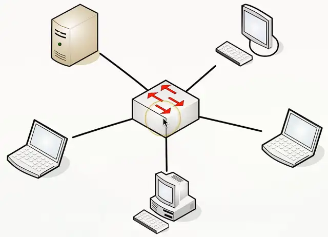
Switching Technologies
VLANs and Trunking
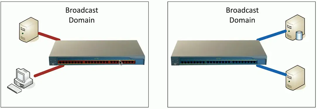
LANs
Local Area Networks
A group of devices in the same broadcast domain
Two switches, taking power
Using double the rack space
Harder to manage
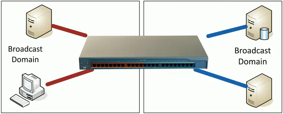
Virtual LANs
Virtual Local Area Networks
A group of devices in the same broadcast domain
Separated logically instead of physically
One switch to manage, less power usage
Cheaper to manage
Lesser rack space
Red and Blue VLANs will not be to communicate between them like physical LANs, except inside the red/blue VLAN only.
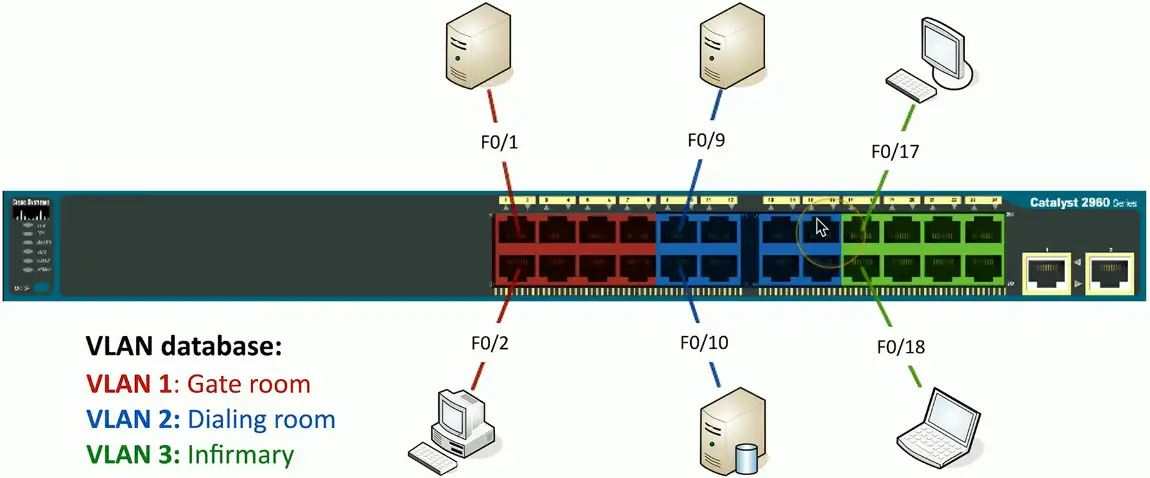
Configuring VLANs
VLAN numbers and names are configured in the switch
The VLAN database
Instead of color, VLANs are represented by number, VLAN1, VLAN2 etc.
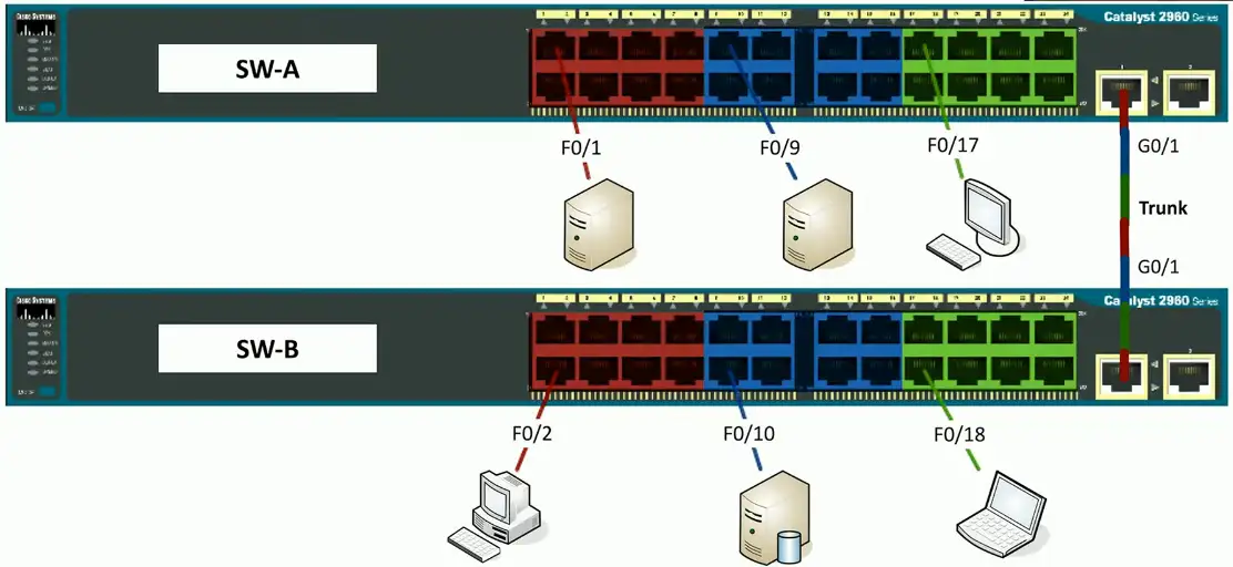
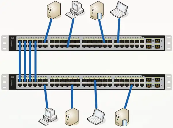
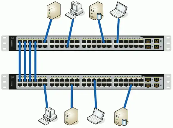
VLANs on multiple switches
We want to communicate among VLAN1s on multiple switches
One simple fix is to connect both VLAN100 on each switch with an Ethernet cable
But, it quickly gets complicated when there are hundreds of switches with VLANs.
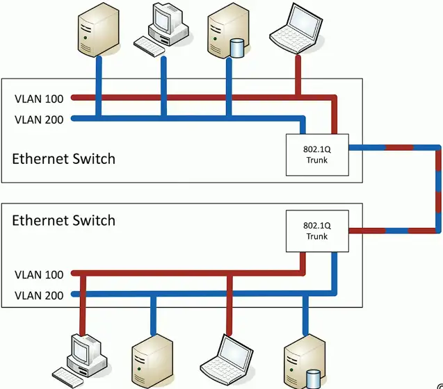
VLAN Trunking
“VLAN trunking is a technology that allows multiple VLANs to share a single physical link between network switches. Instead of needing separate cables for each VLAN, a trunk link carries traffic for all VLANs simultaneously while keeping them logically separated.”
Trunk interface is used to connect VLANs on different physical switches.
Single cable to carry packet for all switches
802.1Q trunking
How trunking identifies which packet belongs to which VLAN interface? By tagging!
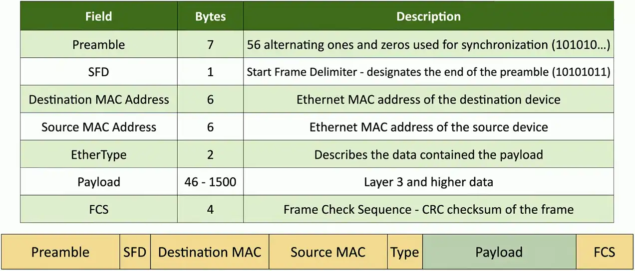
Take a normal Ethernet frame
Add a VLAN header in the frame
VLAN IDs – 12 bits long, 4,096 VLANs
“Normal range” – 1 through 1005, “Extended range” – 1006 through 4094 – 0 and 4,095 are reserved VLAN numbers
Before 802.1Q, there was ISL (Inter-Switch Link)
ISL is no longer used; everyone now uses the 802.1Q standard
VLAN trunking:
VLAN200 wants to send an Ethernet frame to VLAN200 on the other physical switch
VLAN200 sends normal packet to the trunking interface
Trunk adds a tag (VLAN200)
Sends the frame to other VLAN200 device on the different switch
The switch at the other receives the frame, sees the tag VLAN200, removes the tag, and sends it to the VLAN200.
Trunking between switches:
It now needs a single packet to connect VLANs on different physical switches
The Native VLAN
This is different from the “default VLAN”
The default VLAN is the VLAN assigned to an interface by default
Each trunk has a native VLAN
The native VLAN doesn’t add an 802.1Q header
The native VLAN connects switches without a tag
Some devices won’t talk 802.1Q
Just use the native VLAN!
Native VLAN should match between switches
You’ll get a message if the VLAN IDs don’t match
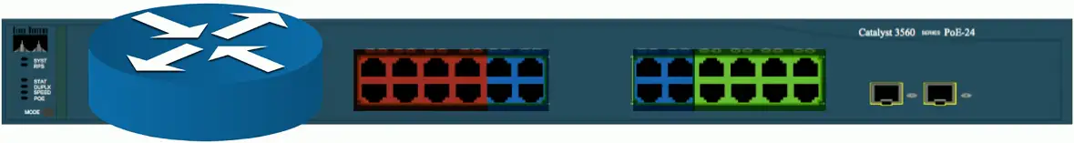
Layer 3 switches
A switch (layer 2) and router (layer 3) in the same physical device
Layer 2 router?
Switching still operates at OSI Layer 2, routing still operates at OSI Layer 3
There is nothing new or special happening here
Just saving a space by putting the switch and router in a single physical device
The internal router connects to the VLANs over VLAN interfaces
Also called switched virtual interfaces (SVI)
May need to enable routing on your switch
Will operate as an L2 device until enabled
May require a switch restart
Doesn’t replace a standalone router
Not all designs require extensive routing
You probably use a layer 3 switch at home
Working with Data and Voice
Old school: Connect computer to switch, connect phone to PBX (Private Branch Exchange)
Two physical cables, two different technologies
Now: Voice over IP (VoIP)
Connect all devices to the Ethernet switch
One network cable for both
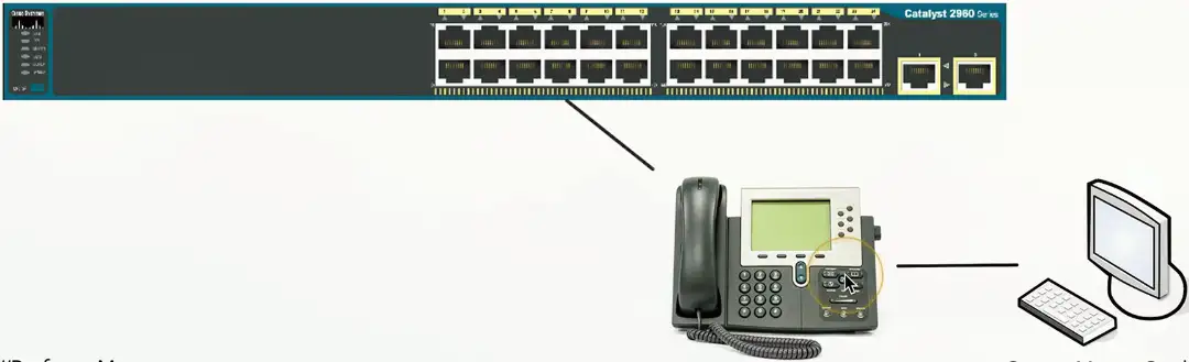
Data and Voice cabling
Computer connects to phone
Phone connects to switch
One cable, one run
Just one problem…
Voice and data don’t like each other
Voice is very sensitive to congestion
Data loves to congest the network
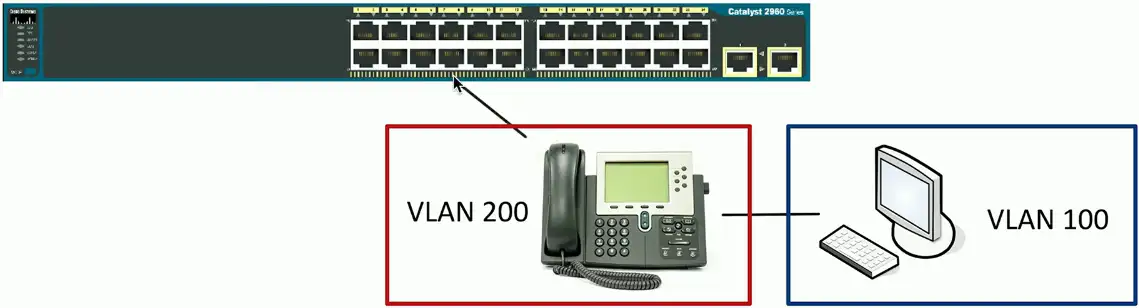
Put the computer on one VLAN and the phone on another
But the switch interface is not a trunk
How does that work?
Each switch interface has a data and a voice VLAN
Configure each of them separately
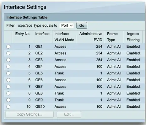
Configuring Voice and Data VLANs
Data passes as a normal untagged access VLAN
Voice is tagged with an 802.1Q header
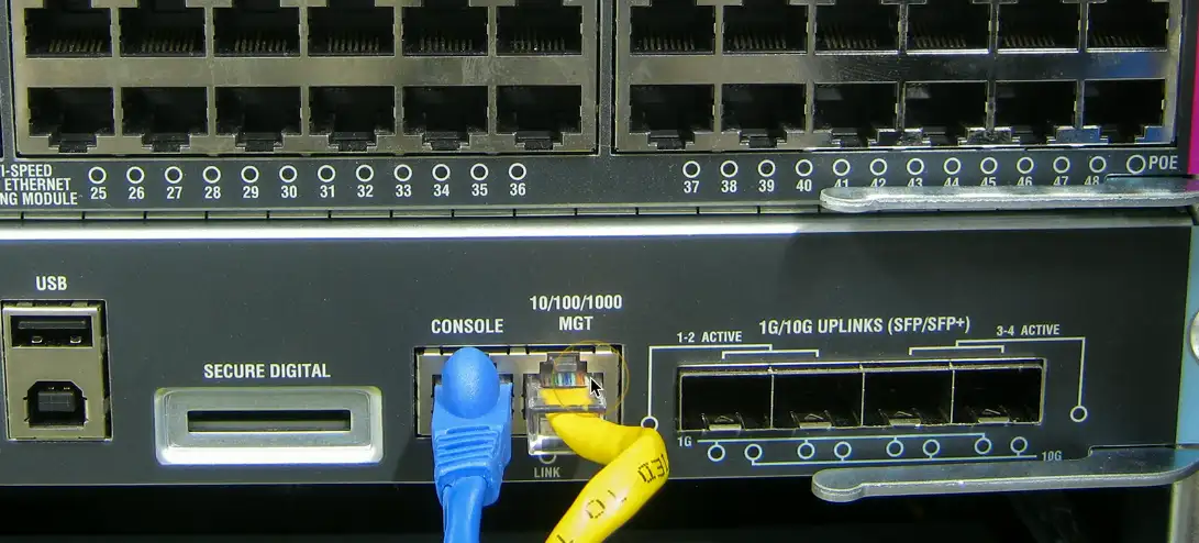
Interface Configuration
Speed and duplex
Speed: 10/100/1,000/10 Gig
Speed mismatch between switches, connection will not work at all.
Duplex Half/Full
Duplex mismatch, the connection will work but with degraded performance
Automatic and manual
Needs to match on both sides
IP address management
Layer 3 interfaces
VLAN interfaces
Management interfaces
IP address, subnet mask/CIDR block, default gateway, DNS (optional)
Link Aggregation
Port bonding/Link aggregation (LAG)
Multiple interfaces act like one big interface
Four 10 Gbits interfaces will act as a single 40 Gbit interface
LACP
Link Aggregation Control Protocol
Adds additional automation and management
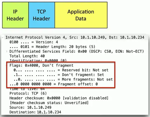
Maximum Transmission Unit (MTU)
Maximum IP packet to transmit
But not fragment
Fragmentation slows things down
Losing a fragment loses en entire packet
Requires overhead along the path
Difficult to know the MTU all the way through the path
Automated methods are often inaccurate
Especially when ICMP is filtered
Jumbo Frames
Ethernet frames with more than 1,500 bytes of payload
Up to 9,216 bytes of an MTU (9,000 is the accepted norm)
Increases transfer efficiency
Per-packet size
Fewer packets to switch/route
Ethernet devices must support jumbo frames
Switches, interface cards
Not all devices are compatible with others
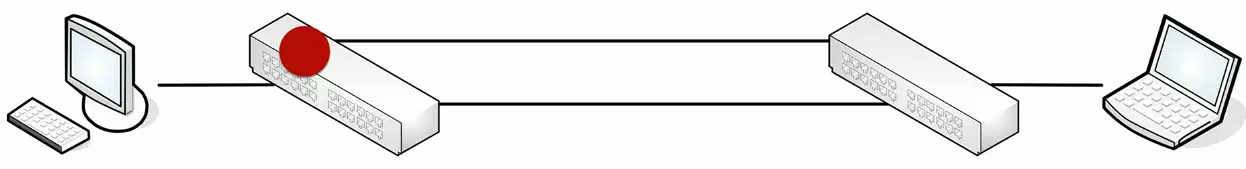
Spanning Tree Protocol
Loop Protection
Connect two switches to each other
Create a loop with two cables
They will send traffic back and forth forever
There’s no “counting” mechanism at the MAC layer
This is an easy way to bring down a network
And somewhat difficult to troubleshoot
Relatively easy to resolve
IEEE standard 802.1D to prevent loops in bridged (switched) networks (1990)
Spanning Tree Protocol
Used practically everywhere
STP Port States
Blocking
Not forwarding to prevent a loop
Listening
Not forwarding and cleaning the MAC table
Learning
Not forwarding and adding to the MAC table
Forwarding
Data passes through and is fully operational
Disabled
Administrator has turned off the port
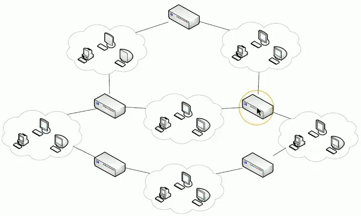
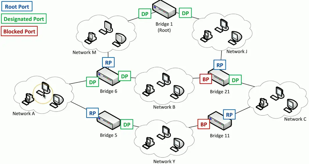
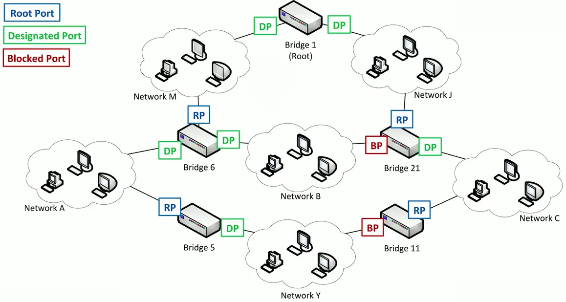
Spanning Tree Protocol
If Network A wants to communicate with Network M, it can use Bridge 6
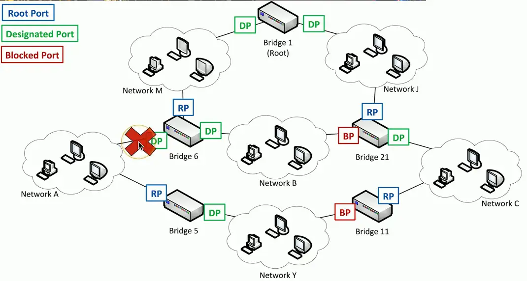
If bridge 6 is unavailable for some reason, there is no other available root!!!
Spanning Tree recognizes the disconnection, and starts relearning the topology of the network, to clear out congestions. It reconfigures the STP port states to reestablish the connection between Network A and Network M through Bridge 5.
RSTP (802.1w)
Rapid Spanning Tree Protocol (802.1w)
A much-needed updated version of STP
This is the latest standard
Faster convergence
From 30 to 50 seconds to 6 seconds
Backwards-compatible with 802.1D STP
You can mix both in your network
Very similar process
An update, not a wholesale change
Wireless Devices
Wireless Technologies
IEEE standards
Institute of Electrical and Electronics Engineers
802.11 committee
Everyone follows these standards
Also referenced as a generation
802.11ac is Wi-Fi 5
802.11ax is Wi-Fi 6 and Wi-Fi 6E (extended)
802.11be is Wi-Fi 7
Future versions will increment accordingly
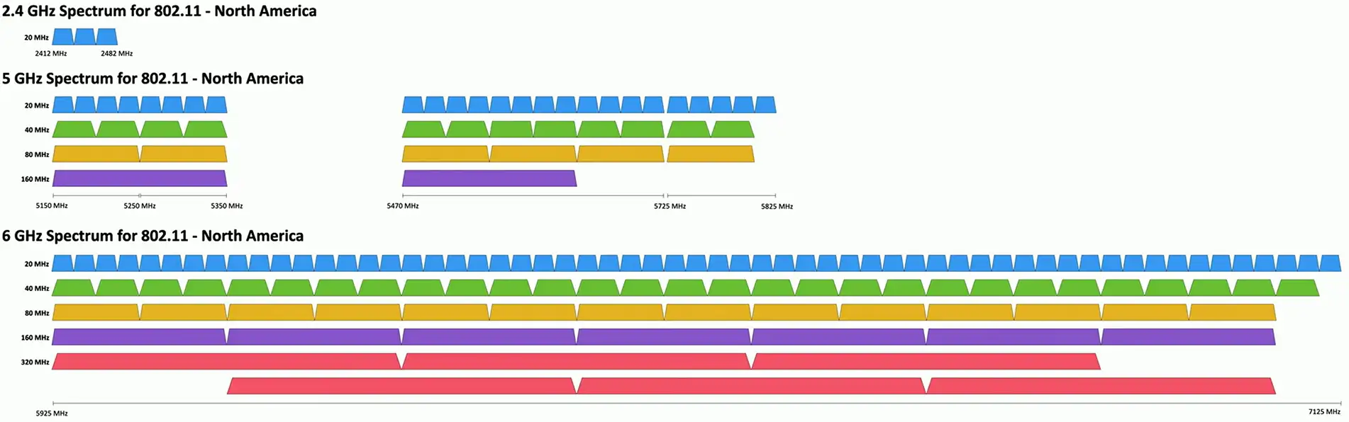
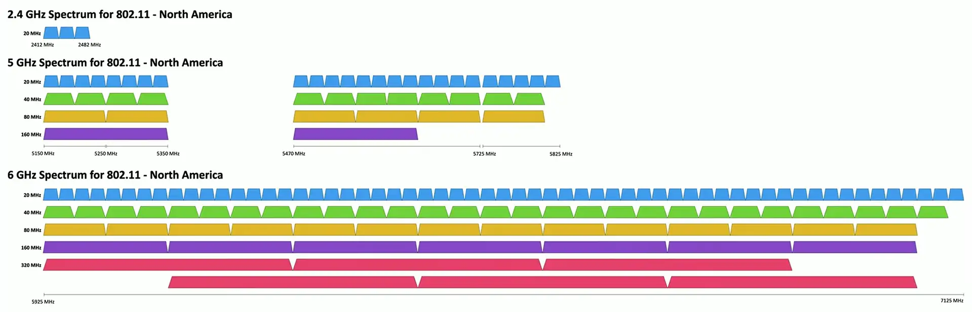
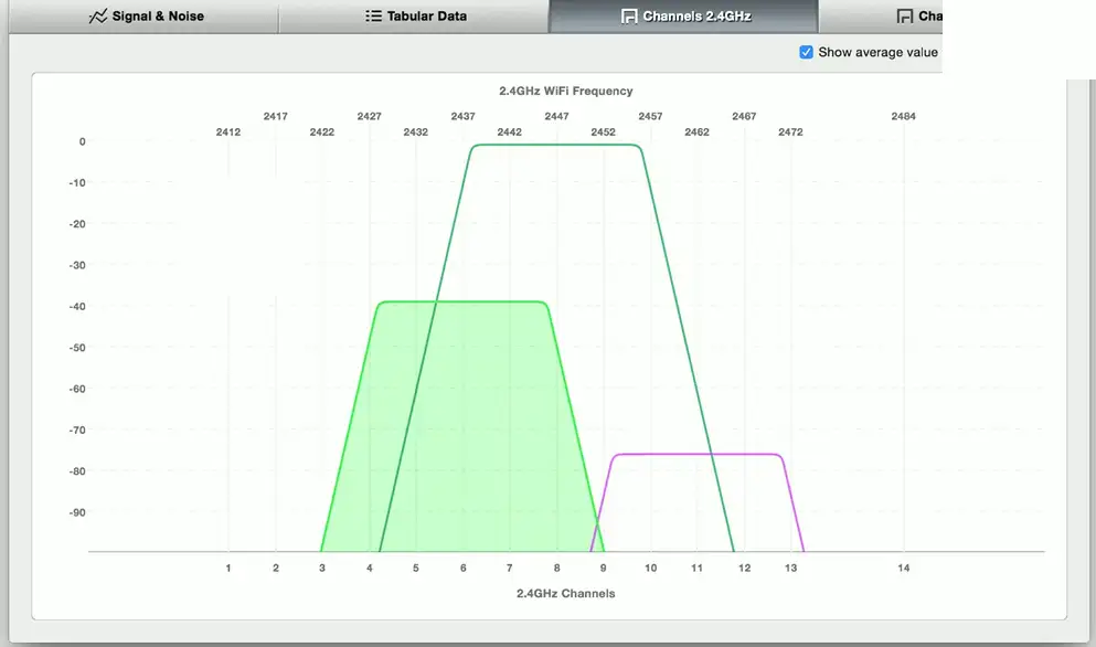
Frequencies
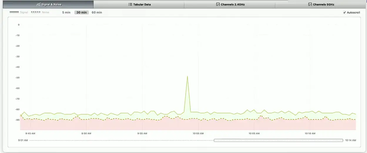
2.4 GHz, 5 GHz, and 6GHz
Sometimes a combination
Channels
Groups of frequencies, numbered by the IEEE
Using non-overlapping channels would be optimal
Bandwidth
Amount of frequency in use
20 MHz, 40 MHz, 80 MHz, 160 MHz
Band Selection and Bandwidth
Band steering
Many frequencies to choose from
Not all of them are optimal
Some devices may only use one frequency
Older devices, specialized systems, etc.
Other devices may have a choice
2.4 GHz, 5 GHz, or 6 GHz
Use band steering to direct clients to the best frequency
2.4 GHz and 5 GHz without band steering = strongest frequency
2.4 GHz and 5 GHz with band steering = 5 GHz connection
Regulatory Impacts
Managing the wireless spectrum is a challenge
Individuals, companies, organizations, countries
The world is constantly changing
Frequency allocations can be fluid
Industry standards are also often worldwide standards
We all have to work together
IEEE 802.11h standard
Add interoperability features to 802.11
The 802.11h standard
802.11 wireless complies with ITU guidelines
A worldwide approach
Now part of the 802.11 standard
DFS (Dynamic Frequency Selection)
Avoid frequency conflict
Access point can switch to an unused frequency
Clients move with the access point
TPC (Transmit Power Control)
Avoid conflict with satellite services
Access point determines power output of the client
Wireless Networking
Independent Basic Service Set (IBSS)
Two devices communicate directly to each other using 802.11
No access point required
Ad hoc
Created for a particular purpose without any previous planning
Without an AP
Temporary or long-term communication
Connect to a device with an ad hoc connection
Configure it with the access point settings and credentials
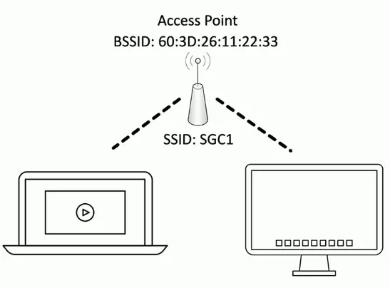
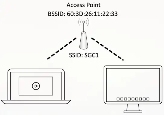
SSID and BSSID
Every wireless network needs a name
SSID (Service Set Identifier)
There might be multiple access points supporting an SSID
How does your computer tell them apart?
The hardware address of an access point is a BSSID (Basic Service Set Identifier)
The MAC (Media Access Control) address
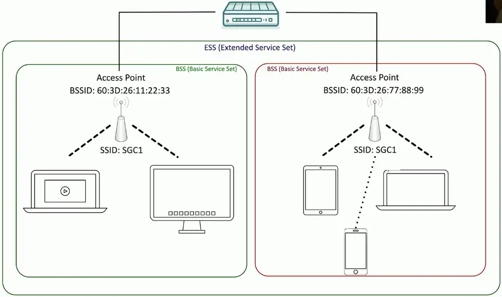
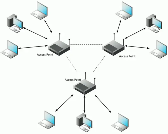
Extending the network
Most organizations have more than one access point
Tens or hundreds
Wireless network names can be used across access points
Makes it easier to roam from one part of the network to another
The network name shared across access points is an ESSID
Extended Service Set Identifier
Your device automatically roams when moving between access points
You don’t have to manually reconnect
ESSID (Extended Service Set Identifier)
Captive Portal
Authentication to a network
Common on wireless network
Access table recognizes a lack of authentication
Redirects your web access to a captive portal page
Username/Password
And additional authentication factors
Once proper authentication is provided, the web session continues
Until the captive portal removes your access (could be 24h timer)
Wireless Security modes
Configure the authentication on your wireless access point/wireless router
Open system
No authentication password is required
WPA/2/3-Personal/WPA/2/3-PSK
WPA2 or WPA3 with a pre-shared key
Everyone uses the same 256-bit key
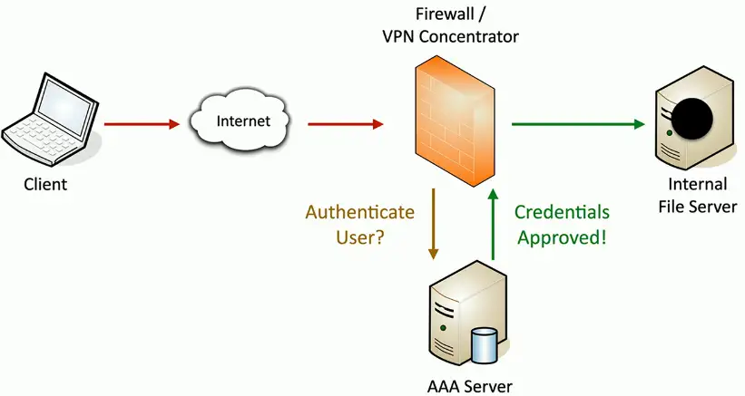
WPA/2/3-Enterprise/WPA/2/3-802.1X
Authenticates users individually with an authentication server (i.e., RADIUS, LDAP, etc.)
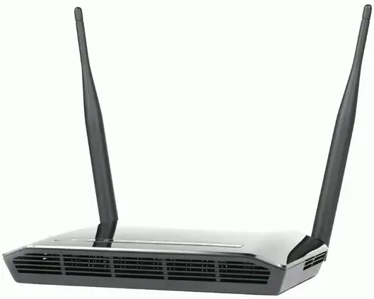
Omnidirectional Antennas
One of the most common
Included on most access points
Signal is evenly distributed on all sides
Omni = all
Good choice for most environments
You need coverage in all directions
No ability to focus the signal
A different antenna will be required
Directional Antennas
Focus the signal
Increased distances
Send and receive in a single direction
Focused transmission and listening
Antenna performance is measured in dB
Double power every 3dB of gain
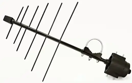
Yagi antenna
Very directional and high gain
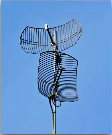
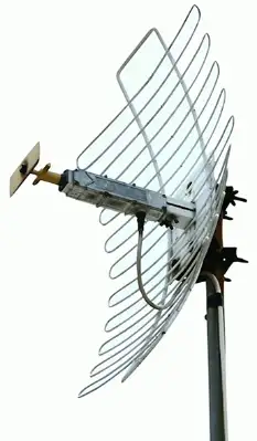
Parabolic antenna
Focus the signal to a single point
Managing Wireless Configurations
Autonomous access points
The access point handles most wireless tasks
The switch is not wireless-aware
Lightweight access points
Just enough to be 802.11 wireless
The intelligence is in the switch
Less expensive
Control and provision
CAPWAP is an RFC standard
Control and Provisioning of Wireless Access Points
Manage multiple access points simultaneously
Wireless LAN Controllers
Centralized management of access points
A single “pane of glass”
Deploy new access points
Performance and security monitoring
Configure and deploy changes to all sites
Report on access point use
Usually a proprietary system
The wireless controller is paired with the access point
Network Types
Wireless mesh
Multiple access points
Access points bridge the gap
Clients across an extended distance can communicate with each other
Ad hoc devices work together to form a mesh “cloud”
Self form and self-heal
Ad hoc mode
Ad hoc
Created for a particular purpose without any previous planning
Without an AP
Two devices communicate directly to each other using 802.11
No access point required
Independent basic service set (IBSS)
Temporary or long-term communication
Connect to a device with an ad hoc connection
Configure it with the access point settings and credentials
Point to point mode
Connect two access points together
Extend a wired network over a distance
Building to building
Site to site
May require specialized wireless equipment
Outdoor antennas and access point
Power adjustments
Frequency options
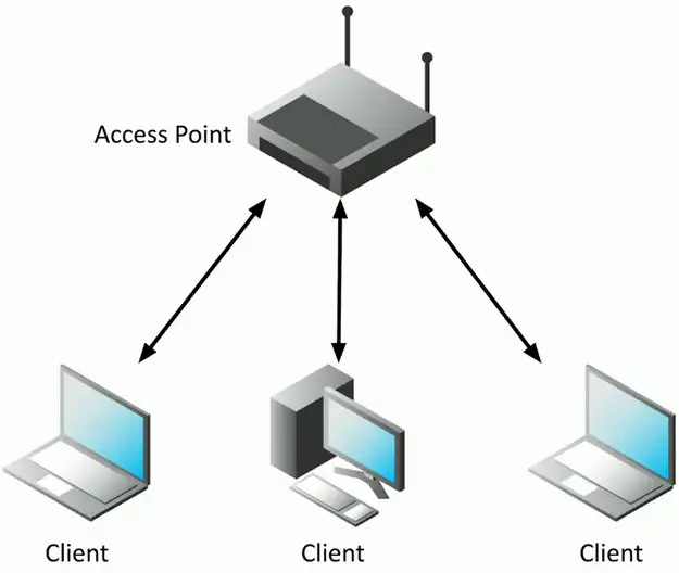
Infrastructure mode
Clients communicate to an access point
Access point forwards traffic
Clients can communicate to a wired network
Access point bridges the networks
Clients can communicate to each other
If the access point allows
Wireless Encryption
Securing a wireless network
An organization’s wireless network can contain confidential information
Not everyone is allowed access
Authenticate the users before granting access
Who gets access to the wireless network?
Username, password, multifactor authentication
Ensure that all communication is confidential
Encrypt the wireless data
Verify the integrity of all communication
The received data should be identical to the original sent data
A message integrity check (MIC)
WPA (Wi-Fi Protected Access)
2002: WPA was the replacement for serious cryptographic weaknesses in WEP (Wired Equivalent Privacy)
Don’t use WEP
Needed a short-term bridge between WEP and whatever would be the successor
Run on existing hardware
WPA2 and CCMP
Wi-Fi Protected Access II (WPA2)
WPA2 certification began in 2004
CCMP block cipher mode
Counter Mode with Cipher Block Chaining Message Authentication Code Protocol, or Counter/CBC-MAC Protocol
CCMP security services
Data confidentiality with AES encryption
Message Integrity Check (MIC) with CBC-MAC
WPA3 and GCMP
Wi-Fi Protected Access 3 (WPA3)
introduced in 2018
GCMP block cipher mode
Galois/Counter Mode Protocol
A stronger encryption than WPA2
GCMP security services
Data confidentiality with AES
Message Integrity Check (MIC) with Galois Message Authentication Code (GMAC)
Physical Installations
Installing Networks
Distribution Frames
Passive cable termination
Punch down blocks
Patch panels
Usually mounted on the wall or flat surface
Uses a bit of real-estate
All transport media
Copper, fiber, voice, and data
Often used as a room or location name
It’s a significant part of the network
Main Distribution Frame (MDF)
Central point of the network
Usually in a data center
Termination point for WAN links
Connects the inside to the outside
Good test point
Test in both directions
This is often the data center
The central point for data
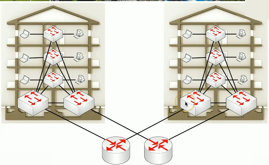
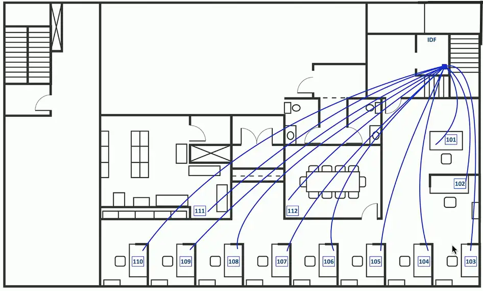
Intermediate Distribution Frame (IDF)
Extension of the MDF
A strategic distribution point
Connects the users to the network
Uplinks from the MDF
Workgroup switches
Other local resources
Common in medium to large organizations
Users are geographically diverse
Equipment racks
Rack sizes
19" rack/device width
Height measured in rack units
1U is 1.75"
A common rack height is 42U
Depth can vary
Often determined by the equipment
Plan and locate
Devices follow standard sizing
Cooling a data center
Heating, Ventilating, and Air conditioning
Thermodynamics, fluid mechanics, and heat transfer
A complex science
Not something you can properly design yourself
Must be integrated into the fire system
Data centers optimize cooling
Separate aisles for heating and cooling
Heat intake and exhaust is important
Front, back, or side
Cale infrastructure
Copper patch panel/patch bay
Punch-down block on one side
RJ45 connector on the other
Move a connection around
Different switch interfaces
The run to the desk doesn’t move
Fiber Distribution Panel
Permanent fiber installation
Patch panel at both ends
Fiber bend radius
Breaks when bent too tightly
Often includes a service loop
Extra fiber for future changes
Inexpensive insurance
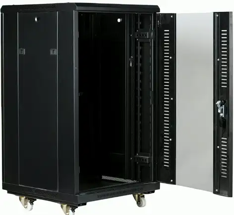
Locking Cabinets
Data center hardware is usually managed by different groups
Responsibility lies with the owner
Racks can be installed together
Side-to-side
Enclosed cabinets with locks
Ventilation on front, back, top, and bottom
Power
WARNING
Always disconnect from the power source when working on a device
Always. Seriously.
Some devices store a charge in capacitors
Know how to discharge before touching
Never connect your body to any part of an electrical system
Do not connect yourself to the ground wire of an electrical system
Respect electricity
It doesn’t respect you
Amp and Volt
Ampere (amp, A) — The rate of electron flow past a point in one second
The diameter of the hose
Voltage (volt, V) Electrical “pressure” pushing the electrons
How open the faucet is
120 volts, 240 volts
Watt
Watt (W)
How much energy is being consumed?
Electrical load is measured in watts
Easy to calculate
Volts × amps = watts
120 V × 0.5 A = 60 W
Current
Alternating current (AC)
Direction of current constantly reverses
Distributes electricity efficiently over long distances
Frequency of this cycle is important
US/Canada – 110 to 120 volts of AC (VAC), 60 hertz (Hz)
Europe — 220-240 VAC, 50 Hz
Direct current (DC)
Current moves in the one direction with a constant voltage
Device power supplies
Devices commonly use DC voltage
Most power sources provide AC voltage
Convert 120 V AC or 240 V AC
To DC voltages
You’ll know when this isn’t working
An important component
UPS
Uninterruptible Power Supply
Short-term backup power
Blackouts, brownouts, surges
Common UPS types
Offline/Standby UPS
Line-interactive UPS
On-line/Double-conversion UPS
Features
Auto shutdown, battery capacity, outlets, phone line suppression
Power distribution units (PDUs)
Provide multiple power outlets
Usually in a rack
Often include monitoring and control
Manage power capacity
Enable or disable individual outlets
Environmental Factors
Humidity
We use a lot of power for data centers
One estimate is nearly 2% of all U.S. power consumption
Humidity level
High humidity promotes condensation
Low humidity promotes static discharge
Industry guidelines for data centers
Somewhere around 40% to 60% humidity
Specific settings vary on location and equipment type
Temperature
Electrical equipment has an optimal operating temperature
Usually part of the device specifications
Industry best practices are around 64 °F (ca. 18 °C) to 81 °F (ca. 27 °C)
Many external influences
Outdoor temperature
Temperature increases as system load increases
HVAC is used to manage temperature and humidity
Sensors are placed in strategic locations
Fire suppression
Data center fire safety
Large area, lots of electronics
Water isn’t the best fire suppression option
Common to use inert gases and chemical agents
Stored in tanks and dispersed during a fire
Many warning signs
Integrated into HVAC system
Monitor for carbon monoxide
Enable/disable air handlers
Processes and Procedures
Network Documentation
Physical Network Maps
Follows the physical wire and device
Can include physical rack locations
Logical Network Maps
Specialized software
Visio, OmniGraffle, Gliffy.com
High level views
WAN layout, application flows
Useful for planning and collaboration
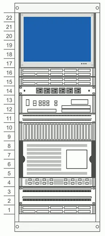
Rack Diagrams
A network admin might never walk into the data center
Physical access is often limited
Provide documentation for installation or change
A picture is worth a thousand words
Detailed digram of rack components
Often listed by physical location of the rack (row 3, rack W)
Each rack unit (U) is documented
Cable maps and diagrams
The foundation of the network
Physical cable and fiber
Valuable documentation
Planning the installation
Numbering each network drop
Troubleshooting after installation
Network Diagrams
Asset management
A record of every asset
Laptops, desktops, servers, routers, switches, cables, fiber modules, tablets, etc.
Associate support tickets with a device make and model
A record of hardware and software
Financial records, audits, depreciation
Make/model, configuration, purchase date, location, etc.
Add an asset tag
Barcode, RFID, visible tracking number, organization name
Asset Database
A central asset tracking system
Used by different parts of the organization
Assigned users
Associate a person with an asset
Useful for tracking a system
Warranty
A different process if out of warranty
Licensing
Software costs
Ongoing renewed deadlines
IP Address Management (IPAM)
Manage IP addressing
Plan, track, configure DHCP
Report on IP address usage
Time of day, user-to-IP mapping
Control DHCP reservations
Identify problems and shortages
Manage IPv4 and IPv6
One console
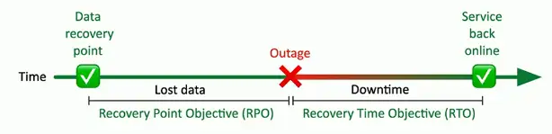
Service Level Agreement (SLA)
Service Level Agreement (SLA)
Minimum terms for services provided
Uptime, response time agreement, etc.
Commonly used between customers and service providers
Contract with an Internet Provider
SLA is no more than four hours of unscheduled downtime
Technician will be dispatched
May require customer to keep spare equipment on-site
Site surveys
Determine existing wireless landscape
Sample the existing wireless spectrum
Identify existing access points
You may not control all of them
Work around existing frequencies
Layout for ongoing site surveys
Plan for ongoing site surveys
Things will certainly change
Heat maps
Identify wireless signal strengths
Life Cycle Management
End-of-life
End of life (EOL)
Manufacturer stops supporting the hardware
May continue to provide security patches and updates
May provide warranty repair
End of support (EOS)
Manufacturer stops updating a product
Current version is the final version
No ongoing security patches or updates
Technology EOS is a significant concern
Security patches are part of normal operation
Patches and bug fixes
Incredibly important
System stability
Security fixes
Service packs
All at once
Monthly updates
Incremental (and important)
Emergency out-of-band updates
Zero-day and important security discoveries
Operating System Updates
Many and varied
Windows, Linux, iOS, Android, etc.
Updates
OS updates/service packs, security patches
User accounts
Minimum password lengths and complexity
Account limitations
Network access and security
Limit network access
Monitor and secure
Anti-virus, anti-malware
Firmware management
The software inside the hardware
The operating system of the hardware device
The potential exists for security vulnerabilities
Upgrade the firmware to non-vulnerable version
Plan for the unexpected
Always have a rollback plan
Save those firmware binaries
Trane Comfortlink II thermostats
Control the temperature from your phone
Trane notified of three vulnerabilities in April 2014
Configuration and real-time session information is constantly synchronized
The failover might occur at any time
Active-active
You bought two devices
Use both at the same time
More complex to design and operate
Data can flow in many directions
A challenge to manage the flows
Monitoring and controlling data requires a very good understanding of the underlying infrastructure
IP Services
DHCP
IPv4 address configuration used to be manual
IP address, subnet mask, gateway, DNS servers, NTP servers, etc.
October 1993 — The bootstrap protocol
BOOTP
BOOTP didn’t automatically define everything
Some manual configurations were still required
BOOTP also didn’t know when an IP address might be available again
Dynamic Host Configuration Protocol
Initially released in 1997, updated through the years
Provides automatic address/IP configuration for almost all devices
DHCP Process
DORA
A four-step process
Discover
Find a DHCP server
Offer
Get an offer
Request
Lock in the offer
Acknowledge
DHCP server confirmation
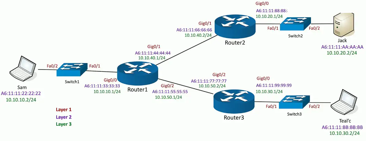
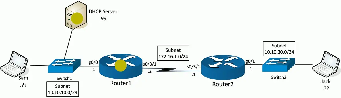
Step 1: Discover
DHCP Discover sent from Sam (0.0.0.0:udp/68) to 255.255.255.255:udp/67
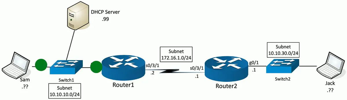
Step 2: Offer
DHCP Offer sent from DHCP Server (10.10.10.99:udp/67) to 255.255.255.255:udp/68
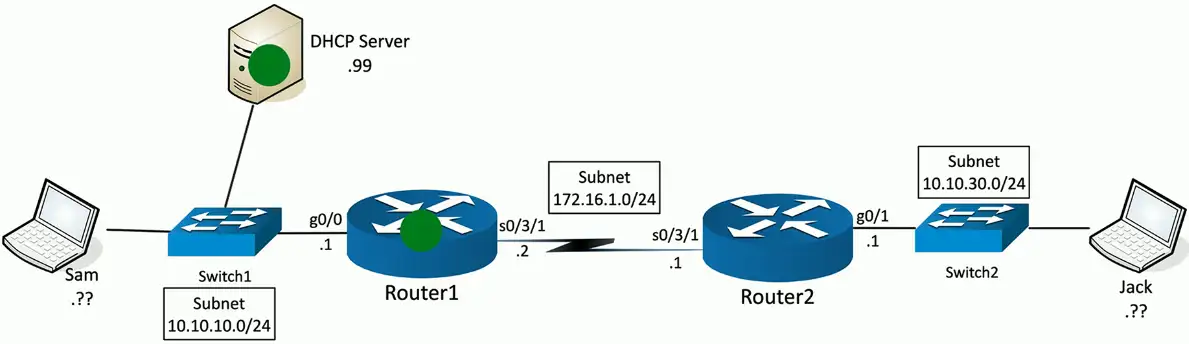
Step 3: Request
DHCP Request sent from Sam (0.0.0.0/udp:68) to 255.255.255.255:udp/67
Step 4: Acknowledgement
DHCP Acknowledgement sent from DHCP Server (10.10.10.99:udp/67) to 255.255.255.255:udp/68
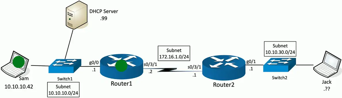
Managing DHCP in the Enterprise
Limited Communication range
Uses the IPv4 broadcast domain
Stops at a router
Multiple servers needed for redundancy
Across different locations
Scalability is always an issue
May not want (or need) to manage DHCP servers at every remote location
You’re going to need a little help(er)
Send DHCP request across broadcast domains
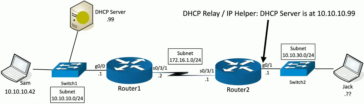
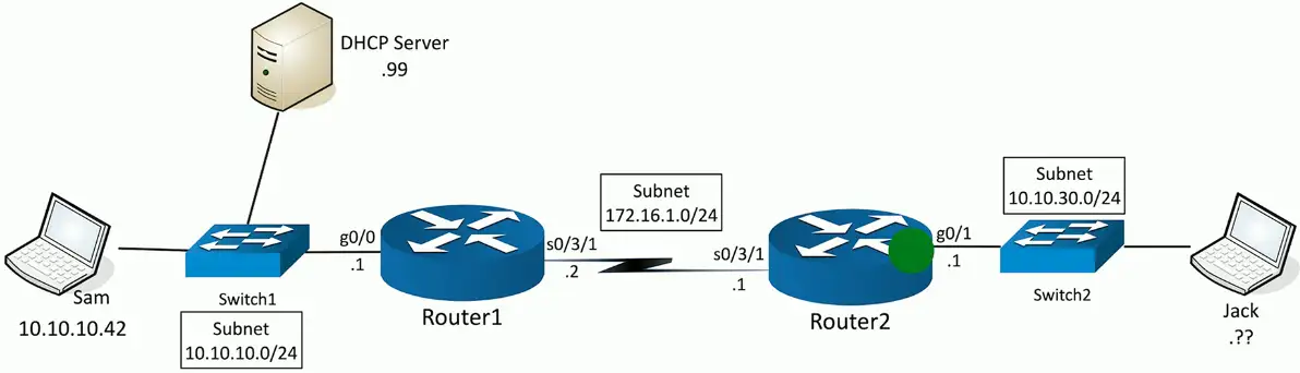
DHCP relay
Discover: DHCP relay changes the source IP address to 10.10.30.1:udp/68 and the destination address to 10.10.10.99:udp/67
Offer with DHCP relay
DHCP offer sent from DHCP Server (10.10.10.99:udp/67) to 10.10.30.1:udp/68
Router with IP helper-address changes the destination IP address to 255.255.255.255, and sent as a broadcast message to local subnet.
The process repeats itself for the remaining two processes, REQUEST/ACKNOWLEDGEMENT through the DHCP relay until, and finally the device gets the IP from the DHCP server.
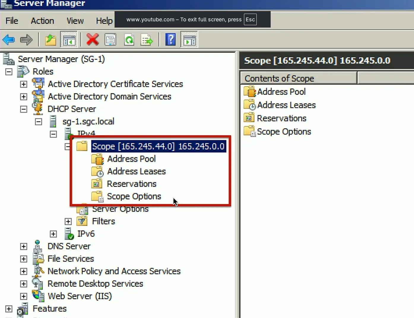
Configuring DHCP
Scope Properties
IP address range
And excluded addresses
Subnet mask
Lease durations
Other scope options
DNS server
Default gateway
VoIP servers
DHCP Pools
Grouping of IP addresses
Each subnet has its own scope
192.168.1.0/24
192.168.2.0/24
192.168.3.0/24
…
A scope is generally a single contiguous pool of IP addresses
DHCP exclusions can be made inside the scope
DHCP address assignment
Dynamic assignment
DHCP server has a big pool of addresses to give out
Addresses are reclaimed after a lease period
Automatic assignment
Similar to dynamic allocation
DHCP server keeps a list of past assignments
You will always get the same IP address
Address reservation
Address reservation
Administratively configured
Table of MAC addresses
Each MAC address has a matching IP address
Other names
Static DHCP Assignment
Static DHCP
IP Reservation
DHCP leases
Leasing your address
It’s only temporary
But it can seem permanent
Allocation
Assigned a lease time by the DHCP server
Administratively configured
Reallocation
Reboot your computer
Confirms the lease
Workstation can also manually release the IP address
Moving to another subnet
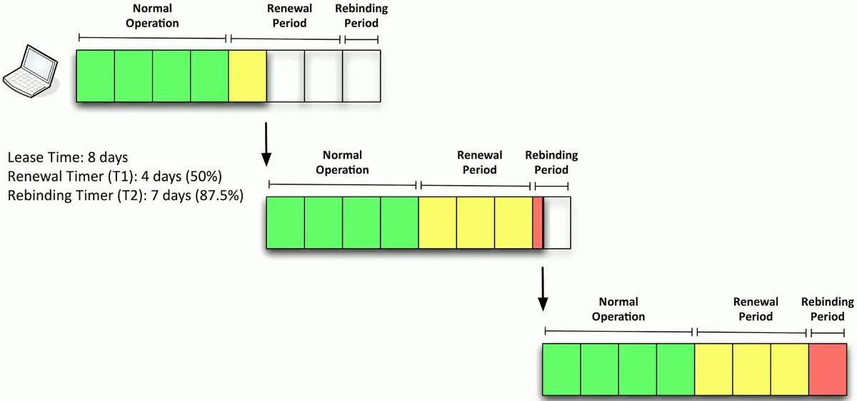
DHCP renewal
T1 timer
Check in with the lending DHCP server to renew the IP address
50% of the lease time (by default)
T2 timer
If the original DHCP server is down, try rebinding with any DHCP server
87.5% of the lease time (7/8ths)
The DHCP lease process
After half-time, T1 timer will be passed, and the device asks for another lease
Another half-period later, T1 timer will be expired, and there is no DHCP server to respond for lease renewal
The device waits until the rebinding period (7/8ths) begins
The device will send another lease request, and enterprise environments have fallback DHCP server configured. The backup DHCP server will get this request and renew the lease period.
DHCP options
A special field in the DHCP message
Many, many options
Options are part of the DHCP RFC
BOOTP called them “vendor extensions”
256 (254 usable) options
O through 255
0 is pad, 255 is end
Many common options
Subnet mask, domain name server, domain name, etc.
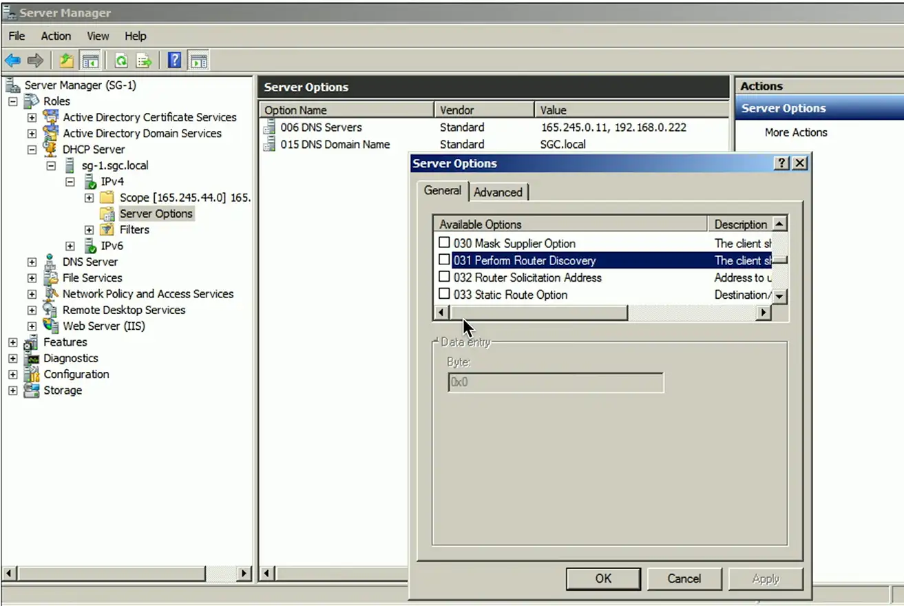
Options are configured on the DHCP server
Not all DHCP servers support option configuration
Options have been added through the years
Option 129: Call Server IP address
Option 135: HTTP Proxy for phone-specific applications
IPv6 and SLAAC
Automatic IP addressing in IPv6
DHCP servers
Similar process as IPv4
Requires redundant DHCP servers
Ongoing administration
Stateless addressing
No separate server keeping the state
No tracking IP or MAC addresses
Lease time don’t exist
NDP (Neighbor Discovery Protocol)
No broadcasts!
Operates using multicast over ICMPv6
Neighbor MAC discovery
Replaces the IPv4 ARP
SLAAC (Stateless Address Autoconfiguration)
Automatically configure an IP address without a DHCP server
DAD (Duplicate Address Detection)
No duplicate IPs!
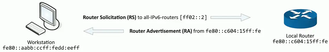
Discover routers
Router Solicitation (RS) and Router Advertisement (RA)
Finding Router
ICMPv6 adds the Neighbor Discovery Protocol
Router also sends unsolicited RA messages
From the multicast destination of ff02::1
Transfers IPv6 address information, prefix value, prefix length, DNS server, etc.
SLAAC (Stateless Address Autoconfiguration)
Determine the IP prefix using NDP (Neighbor Discovery Protocol)
Router Solicitation (RS) and Router Advertisement (RA)
Use the IP prefix with a modified EUI-64 address (or randomize)
Put them together to make a complete IPv6 address
64-bit IPv6 Subnet Prefix
Interface ID
2001:0dn8:0000:0001:
8e2d:aaff:fe4b:98a7
Before using, use NDP’s DAD (Duplicate Address Detection)
Just to be sure you are the only one with that IPv6 address
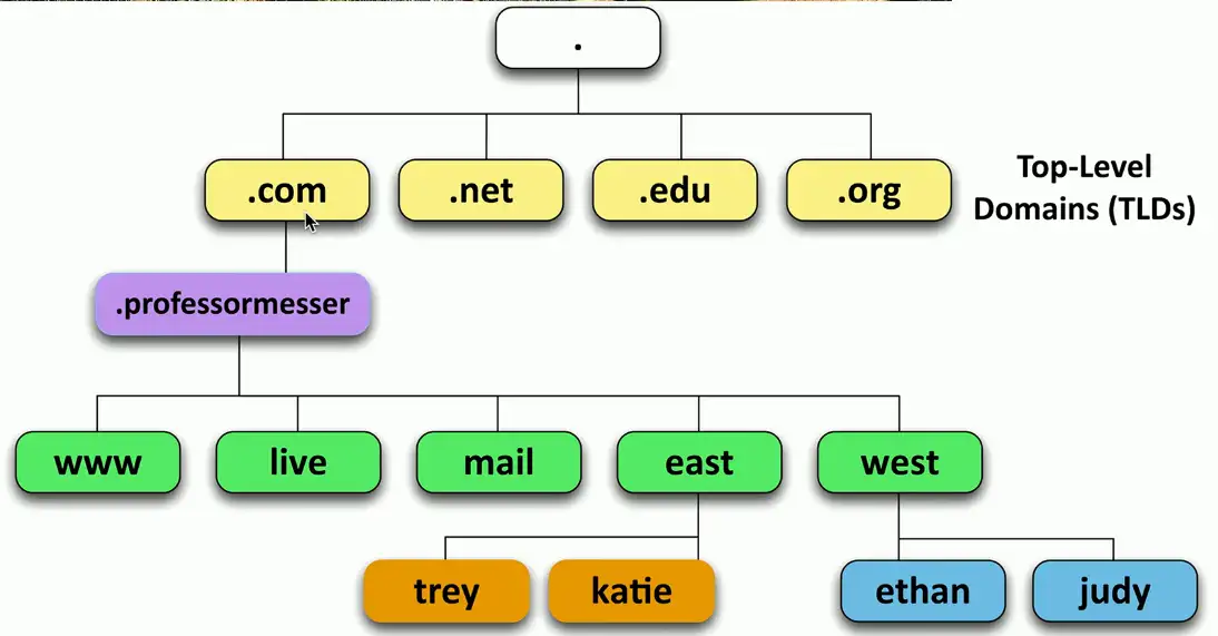
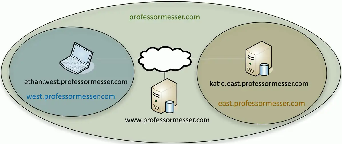
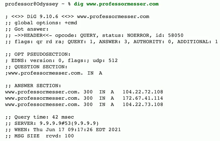
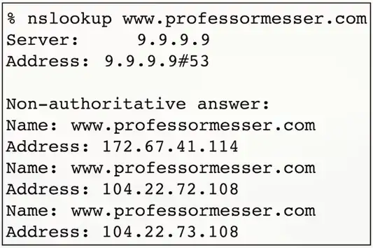
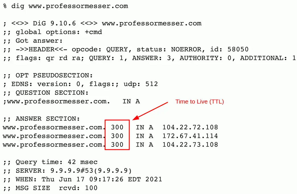
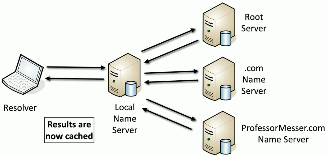
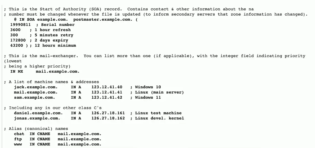
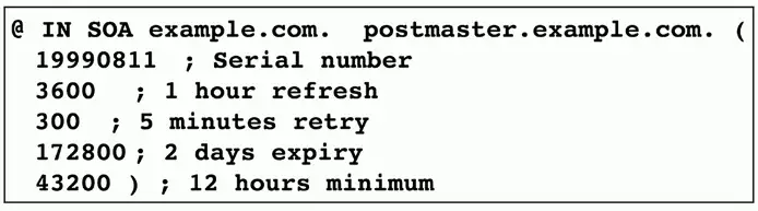
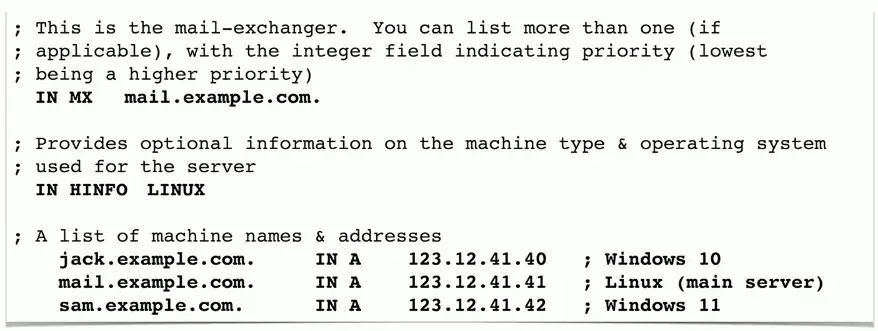
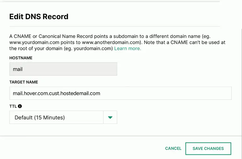
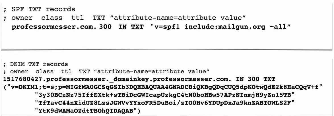
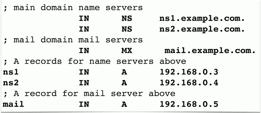
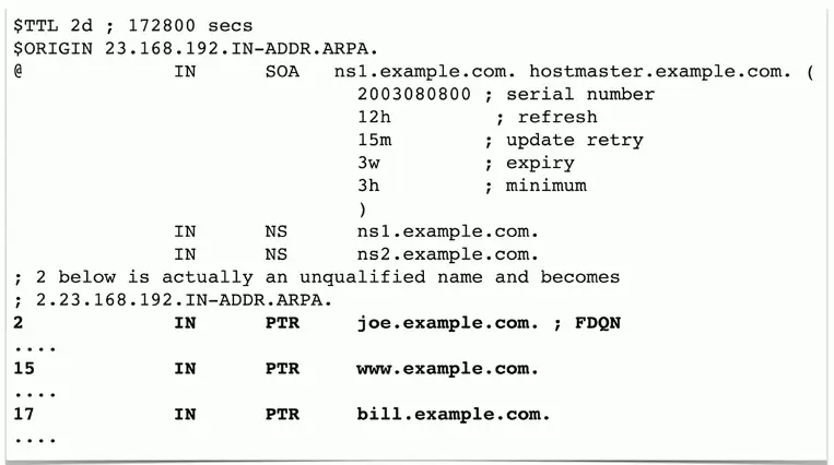
An Overview of DNS
Domain Name System
Translates human-readable names into computer-readable IP addresses
It’s useful to get ahead of any potential problems
Most things have an associated risk
Manage potential risk
Qualify internal and external threats
Risk analysis helps plan for contingencies
Vulnerabilities
A weakness in a system
Allows the bad guys to gain access or cause a security breach
Some vulnerabilities are never discovered
Or discovered after years of use
Many vulnerability types
Data injection
Broken authentication process
Sensitive data exposure
Security misconfiguration
Exploits
Take advantage of a vulnerability
Gain control of a system
Modify data
Disable a service
Many exploit methods
Built to take advantage of a vulnerability
May be complex
Threat
A vulnerability can be exploited by a threat
May be intentional (attacker) or accidental (fire, flood, etc.)
Many of these threats are external to the organization
A resource can have a vulnerability
The vulnerability can be exploited by a threat agent
The threat agent takes a threat action to exploit the vulnerability
The result is a loss of security
Data breach, system failure, data theft
The CIA Triad
Combination of principles
The fundamentals of security
Sometimes references as the AIC triad
Confidentiality
Prevent disclosure of information to unauthorized individuals or systems
Integrity
Messages can’t be modified without detection
Availability
Systems and networks must be up and running
Regulatory Compliance
Compliance
Meeting the standards of laws, policies, and regulations
A healthy catalog of regulations and laws
Across many aspects of business and life
Many are industry-specific or situational
Penalties
Fines, incarceration, loss of employment
Scope
Covers national, territory, or state laws
Domestic and international requirements
Data Localization
Data from a region or country is stored within the borders of that region or country
Data collected in Vegas stays in Vegas
Laws may prohibit where data is stored
GDPR (General Data Protection Regulation)
A complex mesh of technology and legalities
Where is your data stored?
Compliance laws may prohibit moving data out of the country
GDPR — General Data Protection Regulation
European Union Regulation
Data protection and privacy for individuals in the EU
Name, address, photo, email address, bank details, posts on social media, medical information, a computer’s IP address, etc.
Controls personal data
Data collected on EU citizens must be stored in the EU
Users can decide where their data goes
Can request removal of data from search engines
Gives “data subjects” control of their personal data
A right to be forgotten
PCI DSS
Payment Card Industry Data Security Standard (PCI DSS)
A standard for protecting credit cards
Six control objectives
Build and maintain a secure network and systems
Protect cardholder data
Maintain a vulnerability management program
Implement strong access control measures
Regularly monitor and test networks
Maintain an information security policy
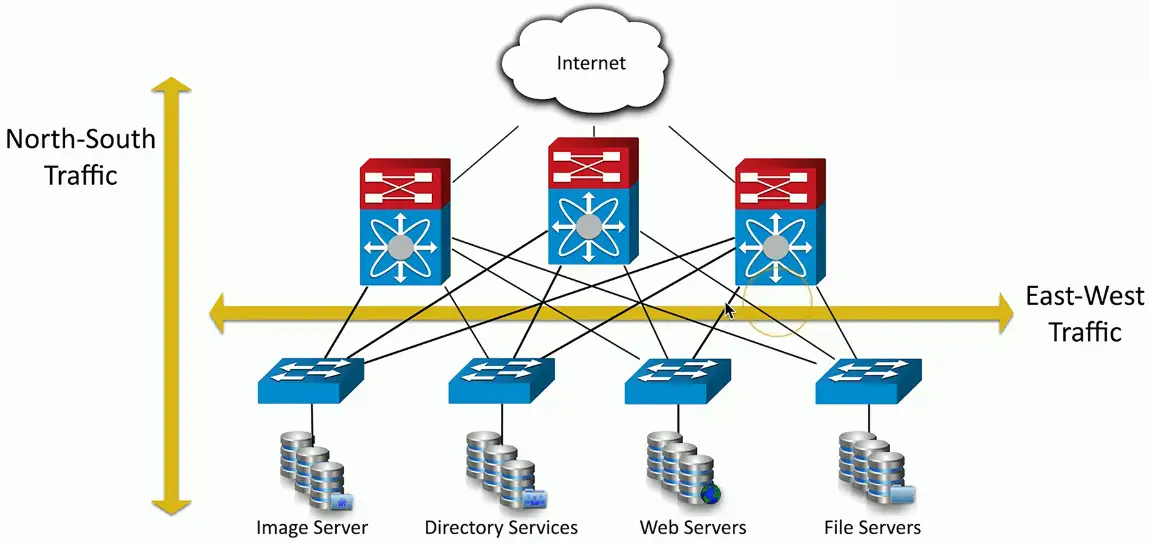
Segmentation Enforcement
Segmenting the network
Physical, logical or virtual segmentation
Devices, VLANs, virtual networks
Performance
High-bandwidth applications
Security
Users should not talk directly to database servers
The only applications in the core are SQL and SSH
Compliance
Mandated segmentation (PCI compliance)
Makes change control much easier
IoT (Internet of Things)
Sensors
Heating and cooling, lighting
Smart devices
Home automation, video doorbells
Wearable technology
Watches, health monitors
Weak defaults
IoT manufacturers are not security professionals
IIoT (Industrial Internet of Things)
IoT for companies
Machine to machine communication
Segmentation is just as important
More data is at stake
Facility automation
Temperature, air quality, lighting
Industrial equipment/ICS monitoring
Oil and gas, robotics, medical devices
Specialized monitoring systems
Wired and wireless connectivity
SCADA/ICS
Supervisory Control and Data Acquisition System
Large-scale, multisite Industrial Control Systems (ICS)
PC manages equipment
Power generation, refining, manufacturing equipment
Facilities, industrial, energy, logistics
Distributed control systems
Real-time information
System control
Requires extensive segmentation
No access from the outside
Operational Technology (OT)
The hardware and software for industrial equipment
Electric grids, traffic control, manufacturing plants, etc.
This is more than a web server failing
Power grid drops offline
All traffic lights are green
Manufacturing plant shuts down
Requires a different approach
A much more critical security posture
Guest Networks
A network for visitors
No access to the private network
Separate wireless network
For guests only
Controlled access
Password or captive portal
Fire walled from the rest of the network
Internet Access only
BYOD
Bring Your Own Device
Bring Your Own Technology
Employee owns the device
Need to meet the company’s requirements
A challenge to secure
Segment the device from the internal network
It’s both a home device and a work device
Attack Types
Denial of Service
Force a service to fail
Overload the service
Take advantage of a design failure or vulnerability
Keep your systems patched!
Cause a system to be unavailable
Competitive advantage
Create a smokescreen for some other exploit
Precursor to a DNS spoofing attack
Doesn’t have to be complicated
Turn off the power
A “friendly” DoS
Unintentional DoSing
It’s not always a ne’er-do-well
Network DoS
Layer 2 loop without STP
Bandwidth DoS
Downloading multi-gigabyte Linux distribution over a DSL line
The water line breaks
Get a good shop vacuum
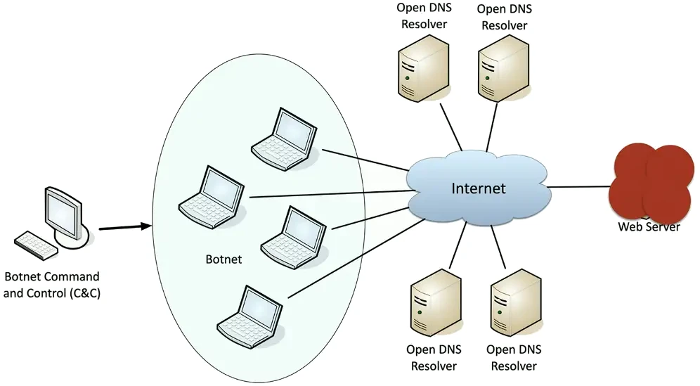
Distributed Denial of Service (DDoS)
Launch an army of computers to bring down a service
Use all the bandwidth or resources — traffic spike
This is why the attackers have botnets
Thousands or millions of computers at your command
At its peak, Zeus botnet infected over 3.6 million PCs
Coordinated attack
Asymmetric threat
The attacker may have fewer resources than the victim
DDoS reflection and amplification
Turn your small attack into a big attack
Often reflected off another device or service
An increasingly common network DDoS technique
Turn Internet services against the victim
Uses protocols with little (if any) authentication or checks
NTP, DNS, ICMP
Simple DNS query returns much more data than simple domain response
A common example of protocol abuse
VLAN Hopping
Define different VLANs
Organizational, network engineering, security
You only have access to your VLAN
Good security best practice
“Hop” to another VLAN
This shouldn’t happen
Two primary methods
Switch spoofing
Double tagging
Switch Spoofing
Some switches support automatic configuration
Is the switch port for a device, or is it a trunk?
There is no authentication required
Pretend to be a switch
Send trunk negotiation
Now you have got a trunk link to a switch
Send and receive from any configured VLAN
Switch administrators should disable trunk negotiation
Administratively configure trunk interfaces and device/access interfaces
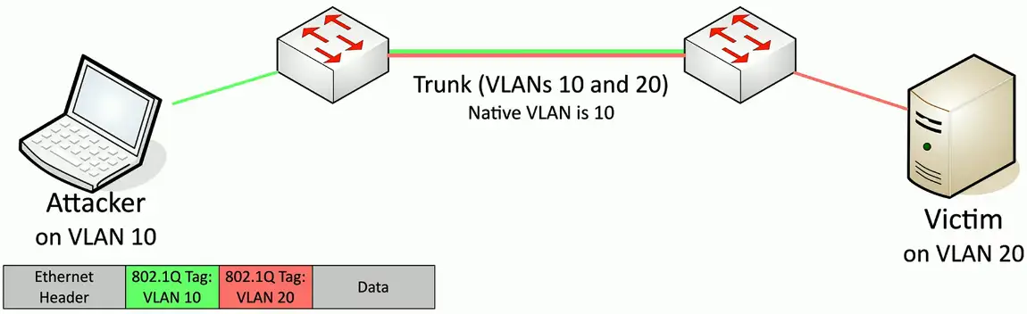
Double Tagging
Craft a packet that includes two VLAN tags
Takes advantage of the “native” VLAN configuration
The first native VLAN tag is removed by the first switch
The second “fake” tag is now visible to the second switch
Packet is forwarded to the target
This is one-way trip
Responses don’t have a way back to the source host
Good for DoS
Don’t put any devices on the native VLAN
Change the native VLAN ID
Force tagging of the native VLAN
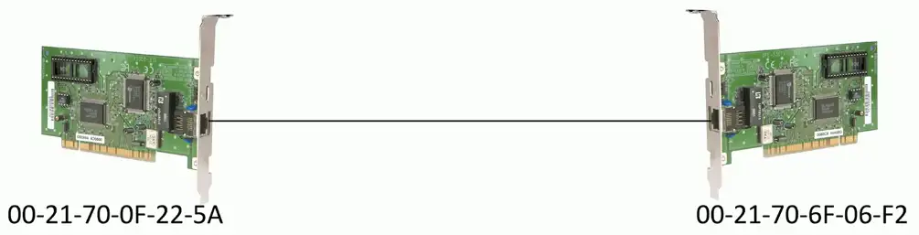
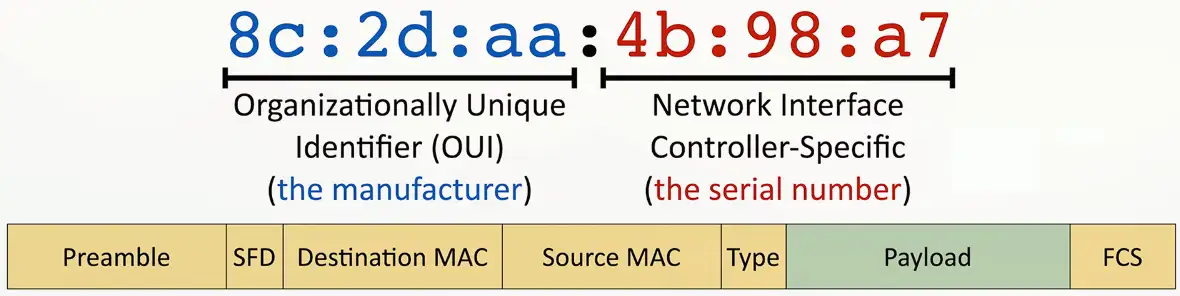
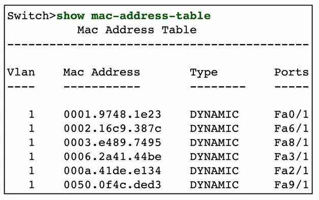
MAC Flooding
The MAC address
Ethernet Media Access Control Address
The “physical” address of a network adapter
Unique to a device
48 bits/6 bytes long
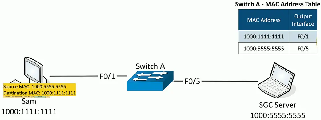
LAN Switching
Forward or drop frames
Based on the destination MAC address
Gather a constantly updating list of MAC addresses
Builds the list based on the source MAC address of incoming traffic
These age out periodically, often in 5 minutes
Maintain a loop-free environment
Using Spanning Tree Protocol (STP)
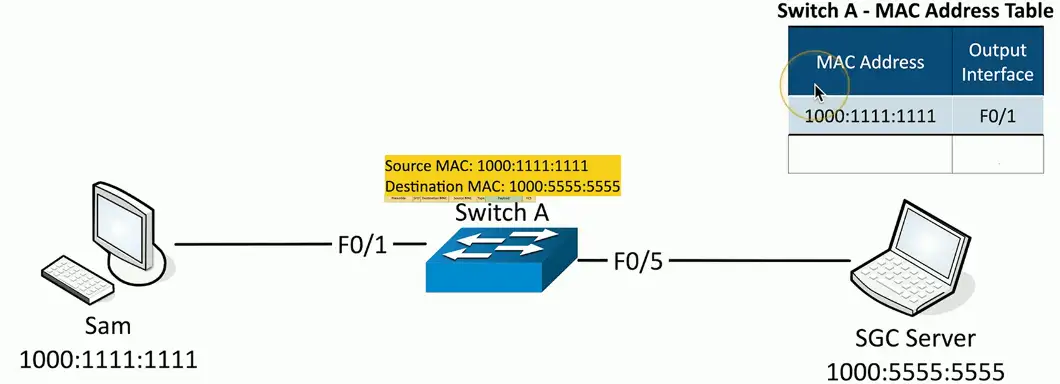
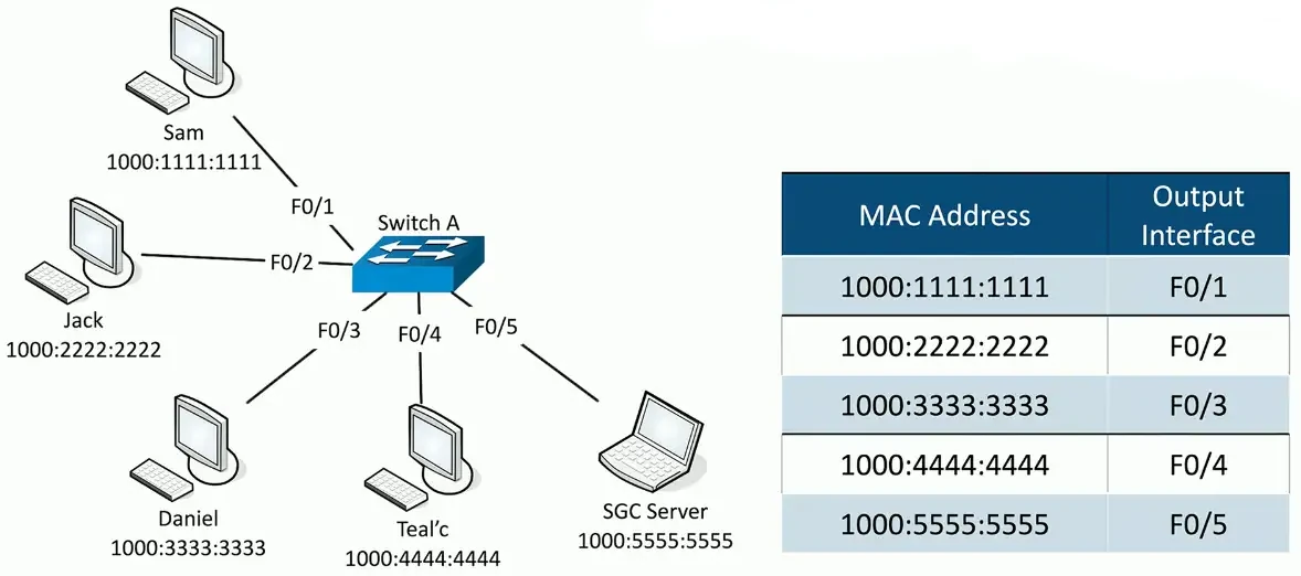
Learning the MACs
Switches examine incoming traffic
Makes a note of the source MAC address
Adds unknown MAC addresses to the MAC address table
Sets the output interface to the received interface
Frame Switching
MAC Flooding
The MAC table is only so big
Attackers starts sending traffic with different source MAC addresses
Force out the legitimate MAC addresses
The table fills up
Switch begins flooding traffic to all interfaces
This effectively turns the switch into a hub
All traffic is transmitted to all interfaces
No interruption in traffic flows
Attacker can easily capture all network traffic!
Flooding can be restricted in the switch’s port security settings
ARP and DNS Poisoning
Spoofing and Poisoning
Pretend to be something you aren’t
Fake web server, fake DNS server, etc.
Email address spoofing
The sending address of an email isn’t really the sender
Caller ID spoofing
The incoming call information is completely fake
On-path attacks
The person in the middle of the conversation pretends to be both endpoints
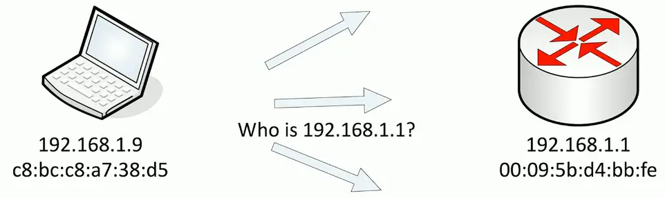
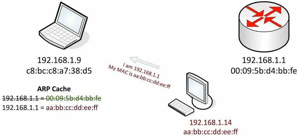
ARP Poisoning (IP Spoofing)
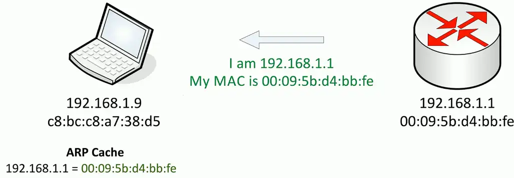
Simple ARP Request and response:
No security or authentication. That’s what the attacker takes advantage of!
The attacker will capture the traffic, and then send to the legitimate target/router. Neither the router nor the client has any idea about the attacker in the middle who is monitoring their traffic.
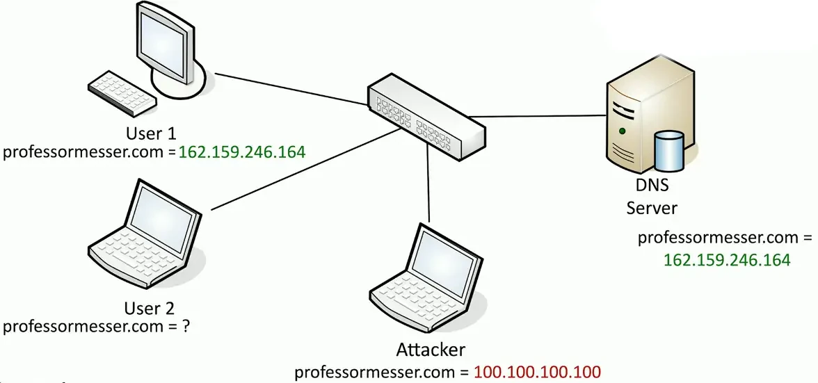
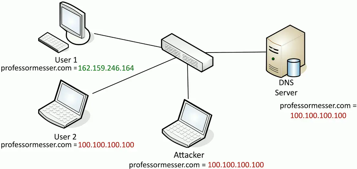
DNS Poisoning
Modify the DNS server
Requires some crafty hacking
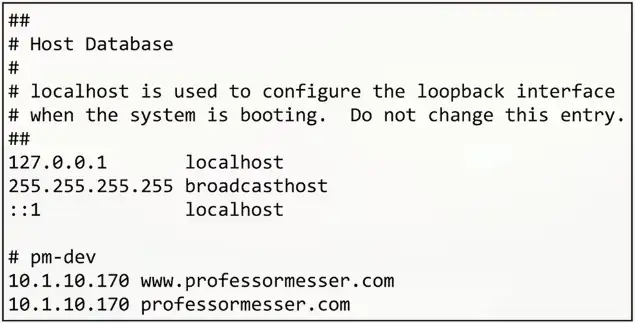
Modify the client host file
The host file takes precedent over DNS queries
Send a fake response to a valid DNS request
Requires a redirection of the original request or the resulting response
Real-time redirection
This is on-path attack
DNS spoofing/poisoning:
Attacker can poison the DNS server:
Rogue Services
Rogue DHCP server
IP addresses assigned by a non-authorized server
There is no inherent security in DHCP
Client is assigned an invalid or duplicate address
Intermittent connectivity, no connectivity
Disable rogue DHCP communication
Enable DHCP snooping on your switch
Authorized DHCP servers in Active Directory
Disable the rogue
Renew the IP lease
Rogue Access Points
An unauthorized wireless access point
May be added by an employee or an attacker
Not necessarily malicious
A significant potential backdoor
Very easy to plug in a wireless AP
Or enable wireless sharing in your OS
Schedule a periodic survey
Walk around your building/campus
Use third-party tools/Wi-Fi Pineapple
Consider using 802.1X (Network Access Control)
You must authenticate, regardless of the connection type
Wireless Evil Twins
Looks legitimate, but actually malicious
The wireless version of phishing
Configure an access point to look like an existing network
Same (or similar) SSID and security settings/captive portal
Overpower the existing access point
May not require the same physical location
Wi-Fi hotspots (and users) are easy to fool
And they are wide open
You encrypt your communication, right?
Use HTTPS and a VPN
On-Path Network Attack
How can an attacker watch without you knowing?
Formerly known as man-in-the-middle
Redirects your traffic
Then passes it on to the destination
You never know your traffic was redirected
ARP poisoning
On-path attack on the local IP subnet
ARP has no security
Other on-path attacks
Get in the middle of the conversation and view or change information